Industrial Valve Basics: Rotary Ball Valves

Ball valve
Cut-away view of ball
valve components:

1) Body
2) Seat
3) Foating ball 
4) Lever handle 
5) Stem

(Image courtesy of Wikipedia)
A ball valve is a rotational motion valve that uses a ball-shaped disk to stop or start fluid flow. The ball, performs the same function as the disk in the globe valve. When the valve handle is turned to open the valve, the ball rotates to a point where the hole through the ball is in line with the valve body inlet and outlet. When the valve is shut, the ball is rotated so that the hole is perpendicular to the flow openings of the valve body and the flow is stopped.

Most ball valve actuators are of the quick-acting type, which require a 90° turn of the valve handle to operate the valve. Other ball valve actuators are planetary gear-operated. This type of gearing allows the use of a relatively small handwheel and operating force to operate a fairly large valve.

Some ball valves have been developed with a spherical surface coated plug that is off to one side in the open position and rotates into the flow passage until it blocks the flowpath completely. Seating is accomplished by the eccentric movement of the plug. The valve requires no lubrication and can be used for throttling service.

Advantages

A ball valve is generally the least expensive of any valve configuration and has low maintenance costs. In addition to quick, quarter turn on-off operation, ball valves are compact, require no lubrication, and give tight sealing with low torque.

Disadvantages

Conventional ball valves have relatively poor throttling characteristics. In a throttling position, the partially exposed seat rapidly erodes because of the impingement of high velocity flow.
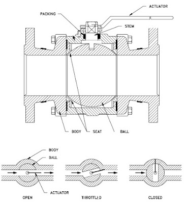
Typical Ball Valve
Typical Ball Valve (click for larger view).

Port Patterns

Ball valves are available in the venturi, reduced, and full port pattern. The full port pattern has a ball with a bore equal to the inside diameter of the pipe.

Valve Materials


Balls are usually metallic in metallic bodies with trim (seats) produced from elastomeric (elastic materials resembling rubber) materials. Plastic construction is also available.

The resilient seats for ball valves are made from various elastomeric material. The most common seat materials are teflon (TFE), filled TFE, Nylon, Buna-N, Neoprene, and combinations of these materials. Because of the elastomeric materials, these valves cannot be used at elevated temperatures. Care must be used in the selection of the seat material to ensure that it is compatible with the materials being handled by the valve.

Ball Valve Stem Design

The stem in a ball valve is not fastened to the ball. It normally has a rectangular portion at the ball end which fits into a slot cut into the ball. The enlargement permits rotation of the ball as the stem is turned.

Ball Valve Bonnet Design

A bonnet cap fastens to the body, which holds the stem assembly and ball in place. Adjustment of the bonnet cap permits compression of the packing, which supplies the stem seal. Packing for ball valve stems is usually in the configuration of die-formed packing rings normally of TFE, TFE-filled, or TFE-impregnated material. Some ball valve stems are sealed by means of O-rings rather than packing.

Ball Valve Position

Some ball valves are equipped with stops that permit only 90° rotation. Others do not have stops and may be rotated 360°. With or without stops, a 90° rotation is all that is required for closing or opening a ball valve.

The handle indicates valve ball position. When the handle lies along the axis of the valve, the valve is open. When the handle lies 90° across the axis of the valve, the valve is closed. Some ball valve stems have a groove cut in the top face of the stem that shows the flowpath through the ball. Observation of the groove position indicates the position of the port through the ball. This feature is particularly advantageous on multiport ball valves.


For more information about any style industrial valve, contact TECO at 800-528-8997 or visit http://www.teco-inc.com.

Industrial Valve Basics: Linear Valves


Parts of a valve
Fig. 1 - Parts of a valve.
A valve is a mechanical device that controls the flow of fluid and pressure within a system or process. A valve controls system or process fluid flow and pressure by performing any of the following functions: 1) Stopping and starting fluid flow; 2) varying (throttling) the amount of fluid flow; 3) controlling the direction of fluid flow; 4) regulating downstream system or process pressure; 5) relieving component or piping over pressure.

There are many valve designs and types that satisfy one or more of the functions identified above. A multitude of valve types and designs safely accommodate a wide variety of industrial applications.

Regardless of type, all valves have the following basic parts: the body, bonnet, trim (internal elements), actuator, and packing. The basic parts of a valve are illustrated in Figure 1.


Valve Body


The body, sometimes called the shell, is the primary pressure boundary of a valve. It serves as the principal element of a valve assembly because it is the framework that holds everything together.

The body, the first pressure boundary of a valve, resists fluid pressure loads from connecting piping. It receives inlet and outlet piping through threaded, bolted, or welded joints.

Valve bodies are cast or forged into a variety of shapes. Although a sphere or a cylinder would theoretically be the most economical shape to resist fluid pressure when a valve is open, there are many other considerations. For example, many valves require a partition across the valve body to support the seat opening, which is the throttling orifice. With the valve closed, loading on the body is difficult to determine. The valve end connections also distort loads on a simple sphere and more complicated shapes. Ease of manufacture, assembly, and costs are additional important considerations. Hence, the basic form of a valve body typically is not spherical, but ranges from simple block shapes to highly complex shapes in which the bonnet, a removable piece to make assembly possible, forms part of the pressure- resisting body.

Narrowing of the fluid passage (venturi effect) is also a common method for reducing the overall size and cost of a valve. In other instances, large ends are added to the valve for connection into a larger line.

Valve Bonnet


The cover for the opening in the valve body is the bonnet. In some designs, the body itself is split into two sections that bolt together. Like valve bodies, bonnets vary in design. Some bonnets function simply as valve covers, while others support valve internals and accessories such as the stem, disk, and actuator.

The bonnet is the second principal pressure boundary of a valve. It is cast or forged of the same material as the body and is connected to the body by a threaded, bolted, or welded joint. In all cases, the attachment of the bonnet to the body is considered a pressure boundary. This means that the weld joint or bolts that connect the bonnet to the body are pressure-retaining parts.

Valve bonnets, although a necessity for most valves, represent a cause for concern. Bonnets can complicate the manufacture of valves, increase valve size, represent a significant cost portion of valve cost, and are a source for potential leakage.

Valve Trim


The internal elements of a valve are collectively referred to as a valve's trim. The trim typically includes a disk, seat, stem, and sleeves needed to guide the stem. A valve's performance is determined by the disk and seat interface and the relation of the disk position to the seat.

Because of the trim, basic motions and flow control are possible. In rotational motion trim designs, the disk slides closely past the seat to produce a change in flow opening. In linear motion trim designs, the disk lifts perpendicularly away from the seat so that an annular orifice appears.


Disk and Seat


For a valve having a bonnet, the disk is the third primary principal pressure boundary. The disk provides the capability for permitting and prohibiting fluid flow. With the disk closed, full system pressure is applied across the disk if the outlet side is depressurized. For this reason, the disk is a pressure-retaining part. Disks are typically forged and, in some designs, hard-surfaced to provide good wear characteristics. A fine surface finish of the seating area of a disk is necessary for good sealing when the valve is closed. Most valves are named, in part, according to the design of their disks.

The seat or seal rings provide the seating surface for the disk. In some designs, the body is machined to serve as the seating surface and seal rings are not used. In other designs, forged seal rings are threaded or welded to the body to provide the seating surface. To improve the wear-resistance of the seal rings, the surface is often hard-faced by welding and then machining the contact surface of the seal ring. A fine surface finish of the seating area is necessary for good sealing when the valve is closed. Seal rings are not usually considered pressure boundary parts because the body has sufficient wall thickness to withstand design pressure without relying upon the thickness of the seal rings.


Stem


The stem, which connects the actuator and disk, is responsible for positioning the disk. Stems are typically forged and connected to the disk by threaded or welded joints. For valve designs requiring stem packing or sealing to prevent leakage, a fine surface finish of the stem in the area of the seal is necessary. Typically, a stem is not considered a pressure boundary part.

Connection of the disk to the stem can allow some rocking or rotation to ease the positioning of the disk on the seat. Alternately, the stem may be flexible enough to let the disk position itself against the seat. However, constant fluttering or rotation of a flexible or loosely connected disk can destroy the disk or its connection to the stem.

Two types of valve stems are rising stems and nonrising stems. Illustrated in Figures 2 and 3, these two types of stems are easily distinguished by observation. For a rising stem valve, the stem will rise above the actuator as the valve is opened. This occurs because the stem is threaded and mated with the bushing threads of a yoke that is an integral part of, or is mounted to, the bonnet.

There is no upward stem movement from outside the valve for a nonrising stem design. For the nonrising stem design, the valve disk is threaded internally and mates with the stem threads.

Rising Stems
Figure 2 - Rising Stems

Nonrising Stems
Figure 3 -Non-rising Stems

Valve Actuator


The actuator operates the stem and disk assembly. An actuator may be a manually operated handwheel, manual lever, motor operator, solenoid operator, pneumatic operator, or hydraulic ram. In some designs, the actuator is supported by the bonnet. In other designs, a yoke mounted to the bonnet supports the actuator.

Except for certain hydraulically controlled valves, actuators are outside of the pressure boundary. Yokes, when used, are always outside of the pressure boundary.

Valve Packing


Most valves use some form of packing to prevent leakage from the space between the stem and the bonnet. Packing is commonly a fibrous material (such as flax) or another compound (such as teflon) that forms a seal between the internal parts of a valve and the outside where the stem extends through the body.

Valve packing must be properly compressed to prevent fluid loss and damage to the valve's stem. If a valve's packing is too loose, the valve will leak, which is a safety hazard. If the packing is too tight, it will impair the movement and possibly damage the stem.

Please contact Thompson Equipment (TECO) with any valve repair, valve automation, or new valve requirement. You can visit TECO at http://www.teco-inc.com or call 800-528-8997.

Process Instrument Calibration

Process Instrument CalibrationCalibration is an essential part of keeping process measurement instrumentation delivering reliable and actionable information. All instruments utilized in process control are dependent on variables which translate from input to output. Calibration ensures the instrument is properly detecting and processing the input so that the output accurately represents a process condition. Typically, calibration involves the technician simulating an environmental condition and applying it to the measurement instrument. An input with a known quantity is introduced to the instrument, at which point the technician observes how the instrument responds, comparing instrument output to the known input signal.

Even if instruments are designed to withstand harsh physical conditions and last for long periods of time, routine calibration as defined by manufacturer, industry, and operator standards is necessary to periodically validate measurement performance. Information provided by measurement instruments is used for process control and decision making, so a difference between an instruments output signal and the actual process condition can impact process output or facility overall performance and safety.

In all cases, the operation of a measurement instrument should be referenced, or traceable, to a universally recognized and verified measurement standard. Maintaining the reference path between a field instrument and a recognized physical standard requires careful attention to detail and uncompromising adherence to procedure.

Instrument ranging is where a certain range of simulated input conditions are applied to an instrument and verifying that the relationship between input and output stays within a specified tolerance across the entire range of input values. Calibration and ranging differ in that calibration focuses more on whether or not the instrument is sensing the input variable accurately, whereas ranging focuses more on the instruments input and output. The difference is important to note because re-ranging and re-calibration are distinct procedures.

In order to calibrate an instrument correctly, a reference point is necessary. In some cases, the reference point can be produced by a portable instrument, allowing in-place calibration of a transmitter or sensor. In other cases, precisely manufactured or engineered standards exist that can be used for bench calibration. Documentation of each operation, verifying that proper procedure was followed and calibration values recorded, should be maintained on file for inspection.

As measurement instruments age, they are more susceptible to declination in stability. Any time maintenance is performed, calibration should be a required step since the calibration parameters are sourced from pre-set calibration data which allows for all the instruments in a system to function as a process control unit.

Typical calibration timetables vary depending on specifics related to equipment and use. Generally, calibration is performed at predetermined time intervals, with notable changes in instrument performance also being a reliable indicator for when an instrument may need a tune-up. A typical type of recalibration regarding the use of analog and smart instruments is the zero and span adjustment, where the zero and span values define the instruments specific range. Accuracy at specific input value points may also be included, if deemed significant.

The management of calibration and maintenance operations for process measurement instrumentation is a significant factor in facility and process operation. It can be performed with properly trained and equipped in-house personnel, or with the engagement of subcontractors. Calibration operations can be a significant cost center, with benefits accruing from increases in efficiency gained through the use of better calibration instrumentation that reduces task time.

TECO's calibration lab is ISO/IEC 17025 Accredited. Many calibration houses can only verify calibration within the manufacturer's specifications, and it's a myth that they can fix anything that is broken.

Services include:

  • ISO/IEC 17025 Accredited Calibrations
  • NIST Traceable Calibrations
  • Live test flows on every meter repair
  • Calibration and Repair of most types of flowmeters including mass meters
  • Flowmeter calibration history files for future comparison
  • Calibration accuracy to factory specifications
  • Calibrations to multiple secondaries and across OEM product lines
  • Multiple test points available
For more information visit http://teco-inc.com or call 800-528-8997 for immediate service.

Consider Remanufactured Process Instrumentation as an Excellent Alternative to Buying New

As the world's largest remanufacturer of magnetic flow meters, TECO has the experience, trained technicians and facilities to remanufacture flanged and wafer mags to meet or exceed all OEM specifications and performance standards.

You will typically have a quotation and failure analysis in your hands by fax/email within 48 hours from the time your instruments arrive on our receiving dock. You will know your instruments are here, you will know what the price and lead time will be, and you can make a timely, informed decision. Send your business to TECO. We make it our job to help you succeed!
  • All Brands
  • NIST Traceable Certificate
  • Off-the-Shelf Meters Available
  • Obsolete Meters our Specialty
  • No Evaluation Charges
  • Magmeter Customization Services
  • All Magmeter accessories
  • New Warranty
  • Failure Analysis
  • Severe Application Meters
  • Converter/Transmitter Repairs
  • Remanufacturing is GREEN

Industrial Valve Actuators and Valve Automation

Pneumatic Valve Actuator
Pneumatic Valve Actuator (white)
Actuators are devices which supply the force and motion to open and close valves. They can be manually, pneumatically, hydraulically, or electrically operated. In common industrial usage, the term actuator generally refers to a device which employs a non-human power source and can respond to a controlling signal. Handles and wheels, technically manual actuators, are not usually referred to as actuators. They do not provide the automation component characteristic of powered units.

The primary function of a valve actuator is to set and hold the valve position in response to a process control signal. Actuator operation is related to the valve on which it is installed, not the process regulated by the valve. Thus a general purpose actuator may be used across a broad range of applications.

Electric Valve Actuator
Electric Valve Actuator (blue)
In a control loop, the controller has an input signal parameter, registered from the process, and compares it to a desired setpoint parameter. The controller adjusts its output to eliminate the difference between the process setpoint and process measured condition. The output signal then drives some control element, in this case the actuator, so that the error between setpoint and actual conditions is reduced. The output signal from the controller serves as the input signal to the actuator, resulting in a repositioning of the valve trim to increase or decrease the fluid flow through the valve.

An actuator must provide sufficient force to open and close its companion valve. The size or power of
the actuator must match the operating and torque requirements of the companion valve. After an evaluation is done for the specific application, it may be found that other things must be accommodated by the actuator, such as dynamic fluid properties of the process or the seating and unseating properties of the valve. It is important that each specific application be evaluated to develop a carefully matched valve and actuator for the process.

Hydraulic and electric actuators are readily available in multi-turn and quarter-turn configurations. Pneumatic actuators are generally one of two types applied to quarter-turn valves: scotch-yoke and rack and pinion. A third type of pneumatic actuator, the vane actuator, is also available.

For converting input power into torque, electric actuators use motors and gear boxes while pneumatic actuators use air cylinders. Depending on torque and force required by the valve, the motor horsepower, gearing, and size of pneumatic cylinder may change.

There are almost countless valve actuator variants available in the industrial marketplace. Many are tailored for very narrow application ranges, while others are more generally applied. Special designs can offer more complex operating characteristics. Ultimately, when applying actuators to any type of device, consultation with an application specialist is recommended to help establish and attain proper performance, safety and cost goals, as well as evaluation and matching of the proper actuator to the valve operation requirements. Share your fluid process control requirements with a specialist in valve automation, combining your own process knowledge and experience with their product application expertise to develop effective solutions.

ABB Rotameters

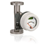
ABB rotameter
ABB rotameter
Rotameters, also known as variable area flowmeters, are designed to measure the flow of liquids or gases via a tapered tube and float system. They are accurate, reliable and simple to install and maintain. The biggest benefit is their low cost, which has made them a popular choice for many flow applications since Fischer & Porter introduced the first mass-produced glass tube flowmeter in 1937. TECO was the first firm to represent and sell the Fischer & Porter Rotameter Line, dating back to March, 1947.

The following brochure is designed to help you select the right ABB rotameter for your application. You can read it below, or download your own copy of the ABB Rotameter brochure from this link. If you have questions or are ready for a quote, simply contact TECO at 800-528-8997 or visit teco-inc.com/ABB.