Startups can be Absolute Hell on Inline Instrumentation


Here’s something you may have experienced before. 

You’ve been down for your scheduled shut down and it’s time to start the process back up.  As the pumps start to circulate, you hear all of that awful knocking as the lines fill and stock starts to move again.

All of a sudden, some of your inline consistency instrumentation goes dead as a doornail.  You pull the sensor out of the line and notice that the sensing element has been bent, or has been completely sheared off.

So what happened? 

Most likely, your inline consistency sensing element just got nailed with a slug of stock that had been dewatering while sitting in the line during your downtime.  At start up, that dewatered slug – or log - started flying down the line as the process was coming up and slammed into your sensor at light speed.

It’s as if you just had a sledge hammer hit your instrument.  No wonder the sensor got damaged, huh?

So, now that you know that, how do you prevent it from happening again?

Here are a couple of ideas:

Install breaker bars both upstream and downstream of your sensor body.  Breaker bars are pieces of dumb metal – ours are cylindrical – that will hopefully break up those dewatered slugs of stock before they slam into your sensor.  It doesn’t work all of the time, of course, but it will work most of the time.  Breaker bars are cheap insurance that should be installed in front and back of every inline sensor in your mill.

By the way, we keep a good supply of these in stock ready to go at a moment’s notice.

A better idea is to install one of our C5000 retractable consistency sensors instead of the one you are currently using.  The C5000 sensor body was designed to be pulled out of the line so that it could be hot swapped while the process is active.  It can also be pulled out of the line during a start up so that dewatered slugs of stock will pass by harmlessly.  The sensing element can then be reinserted in the line once things settle down.

Nifty idea, that.

It Ain’t the Transmitter, Man… well, mostly


A customer of mine recently showed me a competitor’s consistency transmitter that had been installed in one of his pulp lines.  The blade of that transmitter had been snapped clean off and the attachment point was bent about 30 degrees from its normal position.

“Look at that”, he said.  “That’s what I’m talking about when I say I need a more durable sensor.  That’s the third transmitter I’ve had to replace in the last four months and I gotta tell you, I’m getting damn tired of it.  What can you do for me?”.

---

Well, the short answer to that is “it depends”.  It depends on the details of the application because our transmitters, just like everybody elses' transmitters, are designed for a specific range of process conditions.  As long as you’re within the acceptable application window for an instrument, you’re going to get a dependable and durable measurement.  If, however, you stray outside of that range, you’re likely going to get a noisy or bad measurement, or, in extreme cases, a destroyed instrument.

I asked my customer what the conditions were in his line.  He told me that he was running about 4% at 4,000 gpm in a 14” line. Well, that works out to a stock velocity of about 8.337 fps.  Put another way, that’s about 5.6 mph.  While that doesn’t sound very fast, when it comes to instrumentation in a line, 5.6 mph is screamingfast. 

It doesn’t take much in the way of a de-watered stock slug to wreak a lot of damage at that rate.  The reality is I think just about anybody’s transmitter would have been destroyed under those conditions, mine included.

High stock velocities are bad for other reasons, too.  Apart from damage, higher stock velocities can make a transmitter indicate a change in consistency that really isn’t there. 

Mechanical sensors respond to various conditions in the line, of which a change in consistency is only one.  In addition to consistency, transmitter readings are typically a function of flow rate and furnish type, among other parameters.  This means that the reading you’re getting isn’t just giving you information about consistency, but other things as well.

Blade style sensors, in particular, are sensitive to changes in stock velocity.  At high enough speeds, those variations in velocity will look just like shifts in consistency, and woe unto your control loop when that happens.  Your dilution control will try to accommodate for non-existent changes in consistency, and then, the non-existent changes become very real.  The next thing you know, your stock has become really light, or really heavy, all the while there doesn’t seem to be any change on the consistency reading at all.   And if you get really, really heavy, you might lose another transmitter.

You can compensate for higher flow rates – to a point, that is - provided your transmitter accepts a flow input (ours do).  You use the flow information to calculate both the the current velocity and also a correction to the consistency measurement.  Our transmitters are pretty unique in this regard as we are the only manufacturer to incorporate this as a standard feature in our line.

There is a limit to flow compensation, of course.  At very high flow rates, the flow component of the measurement becomes so large that the consistency component is swallowed up in the noise.  Under those conditions, what you really have is a flow indicator and not a consistency transmitter.

The best solution for all of this, of course, is to slow the stock velocity down.  Slower stock velocities will impart less “velocity noise” that you have to compensate for.  In some cases, you can eliminate the flow induced component altogether.  Secondly, slower velocities will also decrease the likelihood of sensor damage. 

There are basically only two ways to reduce stock velocity.  You either slow your production rate down, or you increase the size of the line where you want to make a consistency measurement.  Most mills are in the business of making pulp and paper, so reductions in production rates are usually not an option.  This leaves increasing the line size as the best way to slow the stock velocity down. 

So how much do you want to slow your velocity down?  Well, that depends on the transmitter you want to install.  If you’re looking at TECO’s C3000 or C5000 series sensor, you’ll only need to slow your velocity down to about 2.5 fps or so.  At that rate, the C3000 & C5000 sensor become immune to changes in flow velocity.  In other words, the flow-velocity-induced component of the measurement drops off to zero at rates of 2.5 fps or less.  This value is somewhat variable and dependent on the furnish you’re working with.  For shorter fiber stocks, for example, you could exceed 3.0 fps and not worry too much about velocity noise.

What if you can’t get your velocities below 2.5 fps?  The C3000 & C5000 series sensors are fully compensatable for line velocities up to about 6 fps.  Our C6000 transmitter, don’t forget, accepts a flow input to make this adjustment automatically. 

That said, you’ll get the best results when you keep your velocities below 2.5 fps.

So what did I tell my customer?

I told him that I could provide him with a rugged and durable transmitter that would give him a reliable measurement, provided we made a few changes to his line.  
 

Avoiding Metastable Eddies Part 1


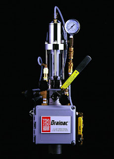
So… you’re thinking about adding a Drainac to your process but you aren’t sure where to put it.  There are a couple things to keep in mind when thinking about placing a Drainac, so let’s go through them now.

Let’s take a look at some of the more important tactical, physical considerations…

First, you want to find a straight length of pipe, at least seven pipe diameters long, without any bends or obstructions in the line.  Why? Well, this has to do with preserving the statistics of sampling.  What we want is for the stock flowing in the line to be in plug flow regime, moving along all nice, straight and even.  This is important because if the stock isn’t flowing all nice and even, i.e., turbulent flow, you might get a sample of stock that isn’t necessarily representative of what’s in the line.  

Turbulent flow can create things like dead spots and metastable eddies (don’t you just love that expression?) and the stock caught in those little whirlpool gems just might be from last week.  And you don’t want to base your refiner loads on stock samples pulled from such places, do you?   Seven pipe diameters pretty much guarantees that you’ll be in plug flow.  Can you get away with smaller lengths of pipe?  Sure, and some customer have successful applications in less than seven PD.  But if you've got seven pipe diameters free, use 'em. 

Second, make sure the line is at least six inches in diameter.  This one is more of a rule of thumb than a hard, fast rule.  The Drainac sample port is two inches in diameter.  If you were to stick this in a four-inch line, you wouldn’t be leaving a whole lot of room for stock to flow by.  That said, we have successfully installed Drainacs in four-inch lines, so it can be done.  It just isn’t a first choice.  I'd rather put in a six-inch spool piece, if space permits.

Here’s another rule of thumb…  if you’re trying to choose between a horizontal line versus an inclined or vertical line, pick the horizontal one.  This has to do with the way that a Drainac cleans itself after an analysis is completed and a horizontal line is better situated for this than an inclined or vertical line.   Again, we do have successful applications in both inclined and vertical lines, so it can be done.

Fourth, and this is really important, make sure that the line is easily accessible for maintenance.  The Drainac has the least maintenance requirement of any freeness analyzer, but it is not, unhappily, maintenance free.  You actually have to clean it from time to time.  If the system is installed in a line that’s thirty feet above the floor and you need to drag a ladder over in order to get to it, you’ll almost always find something else to do when it comes time to clean the system.  If it has to be up in a pipe rack, try and find one that has a scaffold or walkway installed close by.

Fifth, make sure you have a couple of feet of head room on top of the proposed location and a couple feet of cat-slinging room from side to side.  The way you clean a Drainac is to swing it open and you need room to do that.  You don’t want the riser head – or your head, for that matter - banging into another pipe or a ceiling when you open the system.

Sixth, the Drainac needs both air and water, at pressures that are at least 10 psi above the maximum expected pressure in the stock line at all times.  Let me repeat that, at all times.  If you typically run at 40 psi, but will occasionally see 50 psi in the stock line from time to time, then both air and water should be at 60 psi, minimum, at all times.  70 psi would be better, and 80 psi better still.  You get the idea.

While we're on the subject, that air supply should be instrument-quality dry air.  That means a dew point of-40C or better.  Wet air is bad for a Drainac as it can turn the Drainac’s precision pneumatics into boat anchors as pieces-parts get corroded.

That water supply should be filtered as well.  It doesn’t have to be city water, but it should be free of particles larger than 0.007” (80 mesh).  We don’t care if the water is hot or cold – it can be either.  We just want it to be clean.

I have a PowerPoint - actually several of them - on this sort of stuff that I am happy to share with you at any time (webinar, anyone?).  I can also send white papers, bulletins, manuals and so forth.

That covers the main tactical aspects of selecting an installation site.  In my next post, I’ll talk about some of the strategic aspects.

Introducing Mr. Drainac - The Expert on Freeness Measurement

Drainac
The Drainac Automatic
Online Freeness Analyzer
Hi, there. 

My name is Andre Rog and I am, among other things, the Product Engineer for Thompson Equipment Company’s automatic online freeness analyzer, the Drainac™. I’ve been the TECO product engineer for a little over ten years  now, and I’m pretty familiar with all things Drainac. So much so, that I think of myself as Mr. Drainac, a sort of a Bill Nye or Tim Perkins for stock freeness measurement  (Tim is Mr. Science, in case you didn’t know).  

My wife, by the way, is not impressed with my self-appointed role as Mr. Drainac and refuses to be called Mrs. Drainac. I offered Ms. Drainac as an alternative, but she didn’t go for that either. 

As you might imagine, I get a lot of questions on the Drainac. Many of these questions have common themes, so I’ve decided that a blog would be the perfect way to make the answers available to all. Think of this blog as your online resource for Drainac. 

I intend to talk about all things Drainac. How you install one, set one up, calibrate it and so forth. I’ll comment on what you need to do to maintain a Drainac, and what sort of symptoms a sick Drainac might exhibit (and how you fix it). I’ll answer your questions, both frequently asked and otherwise, on any Drainac topic of interest. I’ll also talk about some of the applications for the Drainac, and also how my customers are benefiting by using Drainac. By so doing, I hope to provide some insight as to how you can make the most of your online freeness measurements. 

I invite questions and comments at all times.  If you have a topic you'd like me blog on, please, let me know and I'll do my best.  I can be reached in the USA at (504) 838-3923. My email address is andrer@teco-inc.com. 

By the way, I will also shortly launch a blog on TECO’s consistency transmitter line. Keep an eye out for Mr. Consistency!