Flow Media Identification in Process Piping

Fluid process control operations use pipes to transport materials over distances. Other processing facilities may also employ piping as a conduit to move a variety of other materials. Factory piping networks move liquids and gasses from process point to process point. An accurate indication of the nature and type of substance or material within a pipe, direction of flow, or other pertinent information, contributes to maintaining a safe and effective operation. Pipe marking and color coding should follow recognized applicable standards that are well known to plant operators. 

With pipe marking following a standardized system, employees and contractors on site, and with knowledge of the applicable marking system, are able to easily understand the different colors and their relation to the facility functions. However, some pipes, such as ammonia refrigeration pipes, have their own, independent standards which can be integrated alongside other identifications. Similarly, pipes used in marine environments bear their own standards, along with specific color combinations and banding. Those two sets of standards comply with the hallmarks of general pipe labeling, coloring and identification, including color coding, simple identification of the pipes content, and the inclusion of an accompanying symbol indicating the direction of the flow. For example, a green pipe with white lettering generally means the adjoining pipe contains potable water, potentially for cooling, boiler feeding, or sinks. All combustible fluids are paired with brown labels and white lettering. In addition to the number of predetermined combinations, user defined pipe color combinations are possible so that businesses may plot certain pipes which do not immediately fit within the preset. These can present a challenge, though, due to the fact that user defined color options will require additional instruction to employees and contractors because of their uniqueness to specific businesses. 

The labels used to identify pipes have their own specifications for size and lettering dimensions. Size requirements for the labels allow for companies to create custom labels while still adhering to universal conditions. The size of the pipe markings is related to the pipe diameter, and meant to ensure visibility. An easy way for businesses to translate pipe labels for their employees is to develop and display color code charts. An employee not immediately familiar with the realm of pipe labeling can quickly reference an accurate, accessible chart before taking any action. The maximization of facility safety relies on ensuring that the pipe color labels are visible, unobstructed, and well-lit. Labels placed every 25-50', especially on a pipe that changes direction, near an access point, or near an end point, place information at important junctures on the pipeline. Clearly understanding both the substance a pipe is carrying and, additionally, how individual pipes constitute the facility network is a key way to mitigate potential process hazards.

Blog post courtesy of Thompson Equipment.

Rack and Pinion Pneumatic Valve Actuators

Rack and pinion actuator
(courtesy of Jamesbury)
There are three primary categories of valve actuators commonly used valve automation:
  • Pneumatic
  • Hydraulic
  • Electric
Pneumatic actuators can be further categorized as:
  • Scotch yoke design
  • Vane design
  • Rack and pinion actuators (the subject of this post).
Animation of how rack
and pinion gears convert linear
motion to rotational motion.
Rack and pinion actuators provide a rotational movement designed to open and close quarter-turn valves such as ball, butterfly, or plug valves and also for operating industrial or commercial dampers.

The rotational movement of a rack and pinion actuator is accomplished via linear motion and two gears. A circular gear, referred to a “pinion” engages the teeth of a linear gear “bar” referred to as the “rack”.

Pneumatic actuators use pistons that are attached to the rack. As air or spring power is applied the to pistons, the rack is “pushed” inward or “pulled” outward. This linear movement is transferred to the rotary pinion gear (in both directions) providing bi-directional rotation.


Rack and pinion gear configuration
Actuator rack & pinion gear configuration
Rack and pinion actuators pistons can be pressurized with air, gas, or oil to provide the linear the movement that spins the pinion gear. To rotate the pinion gear in the opposite direction, the air, gas, or oil must be redirected to the other sides of the piston, or use coil springs as the energy source for rotation. Rack and pinion actuators using springs are referred to as "spring-return actuators". Actuators that rely on opposite side pressurization of the rack are referred to as "direct acting".
Most actuators are designed for 100-degree travel with clockwise and counterclockwise travel adjustment for open and closed positions. World standard ISO mounting pad are commonly available to provide ease and flexibility in direct valve installation.

NAMUR mounting dimensions on actuator pneumatic port connections and on actuator accessory holes and drive shaft are also common design features to make adding pilot valves and accessories more convenient.

Pneumatic pneumatic rack and pinion actuators are compact and save space. They are reliable, durable and provide a good life cycle. There are many brands of rack and pinion actuators on the market, all with subtle differences in piston seals, shaft seals, spring design and body designs.

For more information on any pneumatic or electric valve automation project, visit this link or call TECO at 800-528-8997.

Measuring Flow Using Differential Pressure

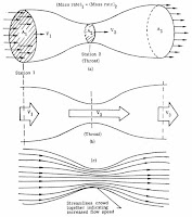
Bernoulli's principle
There are several types of flow instruments that rely on the Bernoulli's principle (an increase in the speed of a fluid occurs simultaneously with a decrease in pressure), that measure the differential pressure across the high pressure side and low pressure side of a constriction.

Many industrial processes adapt this principle and measure the differential pressure across an orifice plate or a Venturi tube to measure and control flow.

An orifice plate is a plate with a hole through it. When placed in the pipe, it constricts the flow and provides a pressure differential across the constriction which can be correlated to the flow rate.

A Venturi tube constricts the flow in the same fashion, but instead a plate with a hole, it uses a pipe or tube with a reduced inner diameter to create the flow differential.

This video provides an excellent basic understanding of how this is accomplished. For more information on any type of industrial flow measuring device, visit the TECO website o call 800-528-8997.

NIST Certification of Flow Instrument Calibration and ISO/IEC 17025 Accreditation

The Thompson Equipment Co., Inc., (TECO) facility is used for performing flow calibration for magnetic flow meters as well as other primary liquid flow measuring devices. It is equipped with both mass and volumetric transfer standards.

The output of a customer owned meter is correlated with the output of a standard volumetric meter over a range of its flow capabilities. Each six months, each volumetric standard meter is calibrated against a mass standard. Each year the mass standards are calibrated against the Louisiana Department of Agriculture Standards Laboratory. 

Also on a periodic basis, standards owned by the LA Dept. of Agriculture are calibrated against the National Institute of Standards and Technology (NIST) Each standard device carries with it the appropriate certificate identifying when its last calibration was performed, and by ID number, which standard device it was calibrated against. 

The NIST Traceable Calibration Certificate from TECO documents this trail of calibration so that the calibration of any flow meter can be confirmed all the way back to the NIST Laboratories as is often required by regulatory agencies, ISO-9000 procedures, etc. This provides the user with a high level of confidence in the readings from his instrument.

ISO/IEC 17025 Accredited


TECO's calibration lab is also ISO/IEC 17025 Accredited, meaning it is in accordance with the recognized International Standard ISO/IEC 17025:2005 General requirements for the competence of testing and calibration laboratories. The TECO laboratory also meets any additional program requirements in the field of calibration. This accreditation demonstrates technical competence for a defined scope and the operation of a laboratory quality management system.

Unlike many calibration houses can only verify calibration within the manufacturer's specifications, TECO can provide a wide range of fully accredited flow calibration services to meet virtually any need.

For more information, contact TECO at 800-528-8997 or visit http://teco-inc.com.