Showing posts with label flow. Show all posts

Impact Weighers - Principle of Operation

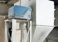
Impact Weigher
Impact weighers are in-line instruments used for weighing of bulk materials. They are designed to measure the force generated by the impact of flowing material on a sensing plate. This force creates a mechanical deflection as it impacts the plate. This deflection is measured by a sensor and converted into an electrical signal. That signal is then processed by an electronic controller, which displays the flow rate and total weight.

Impact Weighers

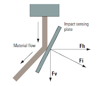
Impact weighers are designed so that the impact plate can only move horizontally. This means that from the total impact force “Fi,” only the horizontal component “Fh” is measured. In the diagram above, “Fv” is ignored. This guarantees that changes in the weight of the sensing plate, due to material build-up or sensing plate wear, will not affect the zero or accuracy of the system.

Impact Weighers
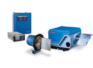
Impact Weighers components
(Thermo Scientific Ramsey)
Advantages:
  • Easy installation in difficult process environments 
  • Measurement is not affected by changing the impact point on the sensing plate • Build-up on the sensing plate cannot influence the zero point
  • High reliability and low maintenance 
  • Mechanical damping system absorbs shocks and damps vibration
  • Sensor allows some overload withoutdamage to the system
  • Sensor is located in a dust-tight enclosureexternal to the process stream 
  • Operates accurately in pulsating or surging flows
To learn more, download the Ramsey DE10 and DE20 Impact Weigher brochure here. For more information, contact TECO by visiting https://teco-inc.com or by calling 800-528-8997.

An Easy Way to Understand Laminar Flow vs. Turbulent Flow

Image courtesy of Wikimedia.org
Laminar flow occurs when a fluid flows in parallel "layers" with no interaction between the layers. When flowing at low velocities, fluids tend to flow without lateral (sideways) mixing, and adjacent layers glide past one another, analogous to playing cards sliding between others in a deck.

In contrast to laminar flow, turbulent flow, caused by excessive kinetic energy in parts of a fluid flow, undergoes mixing and lateral irregularities characterized by eddies, recirculation, and apparent randomness. Fluid speed magnitude and direction changes chaotically in turbulent flow.

The video below provides a very simple, but very effective, demonstration of laminar and turbulent flow.

https://teco-inc.com
800-528-8997

The Coriolis Effect: Understanding How Coriolis Flowmeters Work

The Coriolis effect, a derivative of Newtonian motion mechanics, describes the force resulting from the acceleration of a mass moving to (or from) the center of rotation. As this video demonstrates, the flowing water in a loop of flexible hose that is “swung” back and forth in front of the body with both hands. Because the water is flowing toward and away from the hands, opposite forces are generated and cause the hose to twist. Coriolis flowmeters apply this principle to measure fluid flow. To learn more about the Coriolis effect and how Coriolis flowmeters work, read this earlier post (http://blog.teco-inc.com/2017/01/understanding-coriolis-flow-measurement.html).


Contact TECO for any process flow requirement, including flow meter remanufacturing, custom flow solutions, full service repair, and calibration. http://www.teco-inc.com | 800-528-8997.

Flow Media Identification in Process Piping

Fluid process control operations use pipes to transport materials over distances. Other processing facilities may also employ piping as a conduit to move a variety of other materials. Factory piping networks move liquids and gasses from process point to process point. An accurate indication of the nature and type of substance or material within a pipe, direction of flow, or other pertinent information, contributes to maintaining a safe and effective operation. Pipe marking and color coding should follow recognized applicable standards that are well known to plant operators. 

With pipe marking following a standardized system, employees and contractors on site, and with knowledge of the applicable marking system, are able to easily understand the different colors and their relation to the facility functions. However, some pipes, such as ammonia refrigeration pipes, have their own, independent standards which can be integrated alongside other identifications. Similarly, pipes used in marine environments bear their own standards, along with specific color combinations and banding. Those two sets of standards comply with the hallmarks of general pipe labeling, coloring and identification, including color coding, simple identification of the pipes content, and the inclusion of an accompanying symbol indicating the direction of the flow. For example, a green pipe with white lettering generally means the adjoining pipe contains potable water, potentially for cooling, boiler feeding, or sinks. All combustible fluids are paired with brown labels and white lettering. In addition to the number of predetermined combinations, user defined pipe color combinations are possible so that businesses may plot certain pipes which do not immediately fit within the preset. These can present a challenge, though, due to the fact that user defined color options will require additional instruction to employees and contractors because of their uniqueness to specific businesses. 

The labels used to identify pipes have their own specifications for size and lettering dimensions. Size requirements for the labels allow for companies to create custom labels while still adhering to universal conditions. The size of the pipe markings is related to the pipe diameter, and meant to ensure visibility. An easy way for businesses to translate pipe labels for their employees is to develop and display color code charts. An employee not immediately familiar with the realm of pipe labeling can quickly reference an accurate, accessible chart before taking any action. The maximization of facility safety relies on ensuring that the pipe color labels are visible, unobstructed, and well-lit. Labels placed every 25-50', especially on a pipe that changes direction, near an access point, or near an end point, place information at important junctures on the pipeline. Clearly understanding both the substance a pipe is carrying and, additionally, how individual pipes constitute the facility network is a key way to mitigate potential process hazards.

Blog post courtesy of Thompson Equipment.

Introduction to Transmitters used in Process Control

Flow transmitter
Flow transmitter (ModMag)
Transmitters are process control field devices. They receive input from a connected process sensor, then convert the sensor signal to an output signal using a transmission protocol. The output signal is passed to a monitoring, control, or decision device for use in documenting, regulating, or monitoring a process or operation.

In general, transmitters accomplish three steps, including converting the initial signal twice. The first step is the initial conversion which alters the input signal to make it linear. After an amplification of the converted signal, the second conversion changes the signal into either a standard electrical or pneumatic output signal that can be utilized by receiving instruments and devices. The third and final step is the actual output of the electrical or pneumatic signal to utilization equipment - controllers, PLC, recorder, etc.

Transmitters are available for almost every measured parameter in process control, and are often referred to according to the process condition which they measure. Some examples.

  • Pressure transmitters
  • Temperature transmitters
  • Flow transmitters
  • Level transmitters
  • Vibration transmitters
  • Current, voltage & power transmitters
  • PH, conductivity, dissolved gas transmitters, etc. 
  • Consistency

Consistency Transmitter
Consistency Transmitter(TECO)
Output signals from transmitters, when electrical, often are either voltage (1-5 or 2-10 volts DC) or current (4-20 mA). Power requirements can vary among products, but are often 110/220 VAC or 24 VDC.  Low power consumption by electrical transmitters can permit some units to be "loop powered", operating from the voltage applied to the output current loop. These devices are also called "two-wire transmitters" because only two conductors are connected to the unit. Unlike the two wire system which only needs two wires to power the transmitter and carry the analog signal output, the four-wire system requires four separate conductors, with one pair serving as the power supply to the unit and a separate pair providing the output signal path. Pneumatic transmitters, while still in use, are continuously being supplanted by electrical units that provide adequate levels of safety and functionality in environments previously only served by pneumatic units.

Pressure Transmitter
Pressure
Transmitter
(ifm)
Many transmitters are provided with higher order functions in addition to merely converting an input signal to an output signal. On board displays, keypads, Bluetooth connectivity, and a host of industry standard communication protocols can also be had as an integral part of many process transmitters. Other functions that provide alarm or safety action are more frequently part of the transmitter package, as well.

Wireless transmitters are also available, with some operating from battery power and negating the need for any wired connection at all. Process transmitters have evolved from simple signal conversion devices to higher functioning, efficient, easy to apply and maintain instruments utilized for providing input to process control systems.

To lean more about instrumentation and control, visit http://www.teco-inc.com or call Thompson Equipment at 800-528-8997.
The Operating Principles of a Magnetic Flowmeter

Below is a video, courtesy of Badger Meter, illustrating the operating principles of magnetic flowmeters (also known as magmeters).

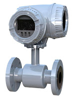
A magnetic field is applied to the flow tube, resulting in an EMF proportional to the flow velocity passing perpendicular to the magnetic flux lines. The physical principle at work is Faraday's law of electromagnetic induction.

Magnetic flow meter requires a conductive fluid, and electrically insulated internal pipe surfaces to operate.

Advantages:
  • Low maintenance cost
  • No moving parts
  • Good for slurry
  • Good for corrosive fluids
  • Very linear
  • Minimal flow restriction

Disadvantages:
  • Requires electrically conductive fluids
For more information on magmeters, visit TECO at http://www.teco-inc.com of call 800-528-8997.

Variable Area Flowmeters (Rotameters)

Rotameter
ABB Rotameter
Variable area flowmeters (rotameters) are the most cost effective solution for almost all applications involving the measurement of industrial process liquids, gases or steam.

They meet the application requirements by featuring a wide range of design varieties and sizes. Technology proven, they offer a long life and high reproducibility. Variable area flowmeters are excellent mechanical back-up meters because no external power supply is needed.

TECO was the first firm to represent and sell the Fischer & Porter Rotameter Line, dating back to March, 1947.  With over 70 years of ABB Rotameter history, TECO is your best source to help with your rotameter applications.   http://www.teco-inc.com | 800-528-8997.

How a Rotameter (Variable Area Flowmeter) Works

Variable Area flowmeter
Components of a Variable Area flowmeter
A rotameter is a flow measuring device that belongs to a group of instruments called variable area flowmeters. For decades Variable Area flowmeters have become established in industrial measurement technology with an economical, mature measurement principle.

The Variable Area flowmeter is an instrument for metering the flowrate of liquids and gases in a pipeline. It includes a vertically oriented conical tube, whose diameter is larger at the top than at the bottom, through which the fluid flows upward and in which a vertically moving float is positioned.

The height of the float in the tube increases as the flowrate increases in such a manner that the resistance to the flow is always balanced by the weight of the float and remains constant regardless of the flowrate. The height of the float in the tube is a measure of the flowrate. The value of the flowrate can be read from a scale.

Variable area flowmeters are the most cost effective solution for almost all applications involving the measurement of industrial process liquids, gases or steam. They meet the application requirements by featuring a wide range of design varieties and sizes. They offer a long life and high reproducibility. Variable area flowmeters are excellent mechanical back-up meters because no external power supply is needed.

For more information on rotameters (variable area flowmeters) visit http://www.teco-inc.com call TECO at  800-528-8997.

Industry Specific Flow Meter Brochures

Industries served by TECO
Industry Specific Flow Measurement Brochures
Here is a listing of flowmeter brochures for specific industries, courtesy of Badger Meter. The brochures provide proven and accepted products for the following markets and applications:

Water & Wastewater Brochure
Water and wastewater treatment facilities have complex operational processes, which involve a wide range of flow measurement tasks. These applications demand the highest flow meter accuracy and reliability, as well as long-term stability and a low cost-of-ownership.

Oil & Gas Brochure
In the oil and gas industry, the flow of liquids and gases must be measured during every phase of exploration, production and transportation. Upstream operations span offshore and onshore activities, including well testing, enhanced oil recovery, fractionation, completion, and separation to recover and prepare crude oil and natural gas.

Chemical & Petrochemical Brochure
Badger Meter products are used across the entire hydrocarbon sector — from upstream production to feedstock for the intermediate stage and downstream processing — in applications ranging from catalyst injection and gas flow measurement, to batching and blending, custody transfer and fugitive emissions monitoring.

HVAC & Building Automation Brochure
You and your customers expect peak performance every day year-round from your HVAC, hydronic chilled/hot water applications and irrigation systems. Products provide accurate measurements, energy calculations and integrated data communications to increase your building’s system performance.

Test & Measurement Brochure
A variety of highly accurate and dependable flow measurement solutions for the demanding test and measurement market.