Showing posts with label flowmeter. Show all posts

Flow Measurement for Hydraulic Fracturing and the Production of Shale Gas

Figure 1. Illustration of the fracing (fracking) process.
(Image courtesy of EPA.gov)
A “conventional” gas reservoir is produced from sands and carbonates (such as limestone). In the conventional reservoir, the gas is in interconnected pore spaces, much like a kitchen sponge, that allow easier flow to a well.  In an "unconventional" gas reservoir, such as shale, the reservoir must be mechanically “stimulated” to create additional permeability and free the gas for collection.  Permeability refers to the capacity of a porous, sediment, soil – or rock in this case – to transmit a fluid. Unconventional reservoirs include tight gas (low-porosity sandstones and carbonate reservoirs) and coal bed methane (CBM – gas produced from coal seams).

For shale gas, hydraulic fracturing (known as "fracing" or "fracking") of a reservoir is the preferred stimulation method (figure 1). This typically involves injecting pressurized fluids to stimulate or fracture shale formations and release the natural gas. Sand pumped in with the fluids (often water) helps to keep the fractures open. The type, composition and volume of fluids used depend largely on the geologic structure, formation pressure and the specific geologic formation and target for a well. If water is used as the pressurized fluid, as much as 20 percent can return to the surface via the well (known as flow back). This water can be treated and reused – in fact, reuse of flow back fluids for subsequent hydraulic fracture treatments can significantly reduce the volume of wastewater generated by hydraulic fracturing. 

The hydraulic fracturing process was used in conventional limestone and sandstone reservoirs for decades before the onset of the shale revolution. But it was not until the 1970s that significant attempts to apply the technology to gas shale were made, pioneered by DOE research and demonstration project cost-sharing with industry in such ventures as the Eastern Gas Shales Project (1976-92).

Another major technology often employed in producing natural gas from shale is horizontal drilling. The shallow section of shale wells are drilled vertically (much like a traditional conventional gas well). Just above the target depth – the place where the shale gas formation exists – the well deviates and becomes horizontal. At this location, horizontal wells can be oriented in a direction that maximizes the number of natural fractures intersected in the shale. These fractures can provide additional pathways for the gas that is locked away in the shale, once the hydraulic fracturing operation takes place.

Accurate flow measurement is important in fracking applications and required for reliable data reporting to supervisory agencies. The preferred technology for measuring flow in fracking applications are magnetic flowmeters (magmeters), primarily for their non-obstructive flow path, accuracy and reasonable cost. There are caveats associated with applying magmeters in fracking applications and selection of specialized flow meter components is required. Fracking sand is very erosive and chemicals mixed with the fracking water can be erosive. Any flow meter used in fracking applications must be rugged enough to withstand these harsh conditions. 

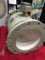
Flow meter designed for fracking
applications (as well as for other
abrasive slurries) by TECO.
An excellent solution that provides all the the virtues of magnetic flowmeters and overcomes performance and longevity issues referred to as "severe service flowmeters" or "slurry flow meters" designed with components matched specifically to withstand the mechanical and chemical abuse they will see. Their modifications include: 
  • A ceramic sleeved liner made of magnesia partially stabilized zirconia. This ceramic can handle the abrasion and chemical attack with very little degradation.
  • Highly polished, ultra-smooth Tungsten electrodes. The Tungsten provides outstanding wear resistance while the high-polish reduces electrical noise introduced in the electrode circuitry.
  • Special coatings, or paints, to provide exterior protection.
For more information on fracking (or fracing) magnetic flow meters, contact Thompson Equipment Company (TECO) by calling 800-528-8997 or visit https://teco-inc.com.


Source: How is Shale Gas Produced? https://www.energy.gov/fe/shale-gas-101

Selecting the Proper Flow Meter: Other Considerations

You Get What You Pay For

Engineers and maintenance personnel who purchase flow meters should remember that accurate instruments cost more based on their features and capabilities. It is always better to search for the type of flow meter best suited to a specific application before sacrificing features in favor of lower cost.

Flow meter specifiers should also take the time to examine long-term ownership costs. It may turn out that flow meters with low purchase prices may be very expensive to maintain. On the other hand, a flow meter with a high purchase price may require little or no service, and therefore lower cost of ownership over time. Lower purchase prices do not always represent the best long term, installed value.

Know Your Process

Users need to closely evaluate their overall process conditions, which include flow rates, pressure and temperature, and operating ranges. Be cautious of lower priced alternatives whose operating parameters don't fully support the requirements of the application.

All flow meters are affected to some extent by the process media and the way they are installed. As a result, their real-time performance will often be different from the controlled reference conditions under which they calibrated. There are some general rules that can be applied to flow meters to assist in reducing uncertainty:
  • For the lowest uncertainty of measurement, positive displacement meters are generally the best option. 
  • Electromagnetic meters provide for the widest flow range and turbine meters are usually the best choice for the highest short-term repeatability.
  • Despite their high initial cost, Coriolis meters are ideal for measuring particularly viscous substances and anywhere that the measurement of mass rather than volume is required.
General Selection Concepts:
  • In general, flow meters with few or no moving parts require less time and attention than more complex flow meters. 
  • Meters constructed with multiple moving parts may malfunction because of dirt, grit or grime present in the process fluid.
  • Flow meters with impulse lines can also plug or corrode.
  • Flow meters with flow dividers and pipe bends sometimes suffer from abrasive media wear and blockages.
  • Swings in ambient temperature may affect the internal dimensions of the flow meter and could require temperature compensation.
Calibration/Recalibration

The need for recalibration of flow meters is generally a function of how well the instrument is paired to its particular application. Should the application be critical, the flow meter accuracy should be checked at frequent, regular intervals. In some instances, mostly non-critical applications, recalibration may not be necessary for a period of years, becuase the application operating parameters never change.

Keep in mind though, that no matter what flow meter technology is chosen, overall system accuracy can never exceed the accuracy of the equipment used to perform the flow meter calibration. With that said, the most precise flow calibration systems on the market employ a positive displacement design. This type of calibrator, directly traceable to the National Institute of Standards and Technology (NIST) via water draw validation, provides total accuracy of at least 0.05 percent.

For more information on flow meter selection, installation, calibration, service, and replacement contact Thompson Equipment Company (TECO). Call them at 800-528-8997 or visit their web site at https://teco-inc.com.

Magnetic Flowmeters for Measuring the Frac Fluid


A piece of equipment used in hydraulic fracturing is the blender truck. It contains the equipment used to prepare and measure the "frac fluid". Frac fluid is composed of water, sand, specialty chemicals, and gels, and is highly erosive and sometimes corrosive. This "blended" mixture of sand, water and chemicals is then injected into a well to hydraulically open cracks in the rock layers below. By opening the cracks, trapped natural gas and petroleum is released and flows more freely. 

Magnetic flowmeters are employed to measure the frac fluid flow and volume.  These flowmeters must accurately meter the frac fluid into the well, stand up to the continual erosive media, and be durable enough to handle the harsh ambient conditions. Standard process magmeters experience shortened lifespans under these conditions and must be pulled from service and repaired. A better alternative is a severe service flowmeters designed specifically for this service.

Thompson Equipment Company (TECO) manufactures an electromagnetic flowmeter (magmeter) designed for frac fluid flow metering. The TECO design incorporates two significant features to improve performance and extend operating life:
  1. A ceramic sleeved liner made of “magnesia partially stabilized zirconia”
  2. The use of solid tungsten electrodes.
The TECO fracing flowmeter provides huge benefits, namely operators save money through increased uptime, they reduce health, safety and environmental risk, and reduce costs related to magmeter replacement and repair.

Remanufactured Process Instruments Save You Money, Resources and Time

TECO is the world's largest remanufacturer of magnetic flow meters, instrumentation and valves. Their secret is the combination of experience, trained technicians and facilities. TECO can remanufacture virtually any process instrument or valve. Every remanufactured item meets or exceeds the original OEM specifications and performance standards.

Send TECO your worn-out flowmeters, instruments and valves and get them back as good as new (or better)!


Thompson Equipment Company
https://teco-inc.com
800-528-8997

Severe Service Flowmeters by TECO

For flow measurement of extremely abrasive slurries in Mining, Dredging, Fracing, and Oil and Gas Exploration.

Capabilities include:
  • Liners: magnesia stabilized zirconia ceramic, aluminum oxide ceramic, polyurethane rubber, neoprene rubber, Linatex, Teflon (PTFE), rotationally molded Tefzel (ETFE), PFA, and others. 
  • Electrodes: SS, Hastelloy C (C-276), Hastelloy B, zirconium, titanium, platinum/iridium, solid tungsten carbide, tungsten carbide coating, etc. 
  • Exotic tube constructions available (100% titanium).
  • Specialty Coatings: epoxy paints, powder coat, custom colors, etc.
800-528-8997

Important Flowmeter Performance Metrics

Animation of differential flow
Common to most flowmeters are rated levels of performance; some of the more universal
performance metrics include accuracy, precision/repeatability, turndown ratio, resolution, ease of installation, straight pipe run requirements, on-going operations and maintenance, and costs.

Accuracy
Accuracy is the difference between a measured value and the actual value. No flowmeter is 100% accurate and most manufacturers provide a range of accuracies in their product line - tighter accuracy requirements are typically more expensive and may also be more restrictive to specific applications.

Precision/Repeatability
The precision or repeatability of a measurement entails the ability to reproduce the same value (e.g., flow rate) with multiple measurements of the same parameter, under the same conditions.

Turndown Ratio
Rotameter
Rotameter
(ABB)
The turndown ratio refers to the flow rates over which a meter will maintain a certain accuracy and repeatability. For example, a steam flow meter that can measure accurately from 1,000 pounds per hour (pph) to 25,000 pph has a turndown ratio of 25:1. The larger the turndown ratio, the greater the range over which the meter can measure the parameter within the accuracy stated.

Resolution
The resolution is the smallest increment of flow that can be incrementally registered by the meter. For example, a water meter designed for a small diameter pipe may be able to provide a resolution of 100 pulses per gallon (or more) as a signal output, but a meter designed for a larger pipe or higher maximum flow may only be able to provide 1 pulse per 100 gallons. Further, a very large flow meter may only be able to provide 1 pulse per 1000 gallons. The metering system may have limitations with regard to peak signal frequency or minimum time between pulses to properly register the data signal.

Ease of Installation
Select make-and-model decisions considering size and weight constraints, specific electrical and communications needs, and the overall environment the flowmeter will operate in.

Magmeter
Magnetic flowmeter
(TECO)
Straight-pipe Run Requirements
Applicable to some types of fluid (gas, liquid and steam) flowmeters, straight-pipe run requirements relate to the length of unobstructed straight pipe required leading up to and immediately following the flow meter’s location. Obstructions in the fluid flow (such as elbows, tees, filters, valves, and sensor fittings) cause changes in the flow pattern (flow regime and velocity profile). Straight-pipe runs allow the flow pattern to normalize/stabilize making measurements by velocity-type and differential-pressure-type flow meters less prone to measurement error. Straight-pipe run requirements are usually expressed in terms of the number of pipe diameters.

The straight pipe requirement is in addition to the length of the flowmeter itself. The straight-pipe run requirements can be reduced with the addition of flow straightening or flow conditioning devices installed upstream.

Ongoing Operations and Maintenance
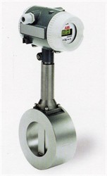
Vortex flowmeter
Vortex flowmeter
(ABB)
The lowest cost flow metering technology may not be the best choice if it has high associated maintenance costs (e.g., frequent service, calibration and recalibration, sensor replacement). As with most capital purchases, a life-cycle cost approach (including all capital and recurring costs) is recommended for decision making.

Installation Versus Capital Cost
In some situations, the cost to install a flowmeter can be greater than the capital cost; this can be true where system shutdowns are necessary for flowmeter installations, or where significant redesign efforts are needed to accommodate a flowmeter’s physical size, weight, or required connection. In these cases, decision makers should consider alternative technologies that may have a higher capital cost but a much lower installed cost. A good example of this is the use of non-intrusive flow metering technologies (e.g., ultrasonic flowmeters) that typically have a high capital cost but often a significantly reduced installed cost. It is recommended that meters be installed with isolation valves or switches making it easier to remove, replace, or service the meter in the future.

Reprinted and abstracted from US Department of Energy paper titled "Metering Best Practices: A Guide to Achieving Utility Resource Efficiency, "

Positive Displacement Flowmeters

Positive displacement flowmeter.
(Badger Meter Blancett)
Positive displacement flowmeters use fluid to mechanically move internal components such as pistons, gears and discs to measure flow.  These devices are both precise and simple to operate.

The positive displacement flowmeter, in contrast with other types of flowmeters, directly measure the volume of fluid passing through the meter instead of employing inferential flow measurement. The rotational velocity of the rotor in the flow meter is directly proportional to the rate of flow. Electronic versions of positive displacement meters rely on magnets to activate sensors in their fluid chambers, whereas their non-electrical counterparts rely on the rotation being driven by the fluid flow.

The operating principle of the positive displacement meter may be simple, yet the flowmeter type offers a few specific advantages for industrial application. A main benefit of this flowmeter is a high level of accuracy due to its internal components. The accuracy of the flowmeter is directly related to the size of the clearances, or the space between the sealing faces.

These flowmeters are also particularly useful for handling a high range of viscosities. As the fluid viscosity increases with the positive displacement meter, less slippage or bypass will occur, meaning more total fluid will pass through the positive displacement meters. In addition to these design-based advantages, the positive displacement meter typically allows for excellent repeatability and linearity.

The longstanding use of positive displacement flowmeters across various industries has been a source of stability in terms of design, with the most recent advancements in positive displacement technology focusing on maintaining precision at lower costs.

There are a few known limitations for the use of positive displacement meters. The meters are not the optimal choice for measuring fluids with large particles, and are also non-ideal for measuring fluids with large air pockets. Additionally, systems using positive displacement meters need to account for slight pressure drops in the positive displacement meter. While the meters are able to accurately measure non-lubricating fluids, using positive displacement flowmeters to measure these types of liquids will not be as efficient as using the flowmeter for lubricating fluids. Overall, these types of flowmeters are a cost effective, accurate and volumetrically based flow measurement solution.

For more information on positive displacement flowmeters, call Thompson Equipment Company (TECO) at 800-528-8997 or visit https://teco-inc.com.


Get Your Process Flow Meters Remanufactured Instead of Buying New

Remanufactured Flow Meters
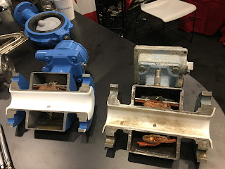
Cutaway before and after of remanufactured flow meter.
Head scratcher. Why buy brand new flow meters when there are companies in the USA that have the trained technicians and facilities ready to remanufacture your old flow meters to a condition better than new?

Remanufactured flow meters meet or exceed all OEM specifications and performance standards. Here's how it works. Experienced technicians break down your flow meter to it's core components - flowtube, electronics, enclosure, flanges, and electrical. All parts are evaluated for wear and tear. All components are cleaned, primed, and painted. New electronics, flow sensors, liners, and electrical connections are installed. Once assembly is complete, the "remanufactured" flow meter goes through an exhaustive quality control process and is calibrated to NIST traceable standards using an advanced, state-of-the-art calibration facility.

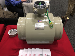
remanufactured flow meter
Remanufactured flow meter.
All this is done very efficiently, quickly and cost-effectively.  You just ship your old instrument in to the attention of the "Repair Department". No RMA is required. The company evaluates your old flow meter and then generates a quote with delivery time for the remanufactured meter (normally within 48 hours).

Here is a summary of the benefits for choosing remanufacturing:
  • All brands of flow meters are candidates.
  • NIST traceable certificate is provided.
  • Obsolete flow meters are no problem.
  • No evaluation fees charged.
  • Accessories are included.
  • New warranty is given.
  • Failure analysis is provided.
  • Flow meters can be repurposed for severe service (enhanced during remanufacturing).
  • Remanufacturing is GREEN and environmentally friendly.
For more information, visit this flow meter remanufacturing link or call 800-528-8997.

Get Your Worn Out Process Instrumentation Remanufactured by TECO

As the world’s largest remanufacturer of instrumentation, TECO has the experience, trained technicians, and facilities to remanufacture your equipment to meet or exceed all OEM specifications and performance standards. Send us your overworked instrument and we'll send it back to you as good as new, and ready for action!
  • All Brands
  • NIST Traceable Certificate
  • Off-the-Shelf Meters Available
  • Obsolete Meters our Specialty
  • No Evaluation Charges
  • Magmeter Customization Services
  • All Magmeter accessories
  • New Warranty
  • Failure Analysis
  • Severe Application Meters
  • Converter/Transmitter Repairs
  • Remanufacturing is GREEN

Instrument Remanufacturing, Custom Flow Solutions, Full Service Repair, Calibration, and Valve Automation Center.  https://www.teco-inc.com | 800-528-8997

World's First Magnetic Flowmeter Developed Specifically for Hydraulic Fracing

When suspended solids are mixed with a liquid (such as water), a mud-like substance referred to as a “slurry” is formed. Slurries are challenging because of their abrasive nature. Add a highly caustic or acidic condition to the slurry, and the magnetic flowmeters (Magmeters) used to measure flow become particularly susceptible to failure. In these situations off-the-shelf magnetic flowmeters won’t last, so consideration must be given to custom flowmeters built specifically to withstand the application’s unique requirements. Hydraulic fracturing (fracing) is one industry where the movement and handling of slurries is very common, and specially designed Magmeters should be used.

Thompson Equipment (TECO) is now offering their "Severe Application Meter (SAM)" (patent pending) which is specifically designed as the world's first Magmeter developed specifically for the hydraulic fracing industry. It is designed with an impact and wear resistant ceramic liner, solid tungsten carbide billet electrodes, and quick change Victaulic flanges. The SAM can also be retrofitted to the customers existing electronic secondary system, such as Rosemount, E+H, Yokagawa, etc.

For more information, contact TECO by calling (504) 833-6381 or by visiting https://www.teco-inc.com.

Consider Remanufactured Process Instrumentation as an Excellent Alternative to Buying New

As the world's largest remanufacturer of magnetic flow meters, TECO has the experience, trained technicians and facilities to remanufacture flanged and wafer mags to meet or exceed all OEM specifications and performance standards.

You will typically have a quotation and failure analysis in your hands by fax/email within 48 hours from the time your instruments arrive on our receiving dock. You will know your instruments are here, you will know what the price and lead time will be, and you can make a timely, informed decision. Send your business to TECO. We make it our job to help you succeed!
  • All Brands
  • NIST Traceable Certificate
  • Off-the-Shelf Meters Available
  • Obsolete Meters our Specialty
  • No Evaluation Charges
  • Magmeter Customization Services
  • All Magmeter accessories
  • New Warranty
  • Failure Analysis
  • Severe Application Meters
  • Converter/Transmitter Repairs
  • Remanufacturing is GREEN

Steam Flow Metering and Measurement

Steam Flow Metering and Measurement
For steam, energy is primarily contained in the latent heat and, to a lesser extent, the sensible heat of the fluid. The latent heat energy is released as the steam condenses to water. Additional sensible heat energy may be released if the condensate is further lowered in temperature. In steam measuring, the energy content of the steam is a function of the steam mass, temperature and pressure. Even after the steam releases its latent energy, the hot condensate still retains considerable heat energy, which may or may not be recovered (and used) in a constructive manner. The energy manager should become familiar with the entire steam cycle, including both the steam supply and the condensate return.

When compared to other liquid flow measuring, the measuring of steam flow presents one of the most challenging measuring scenarios. Most steam flowmeters measure a velocity or volumetric flow of the steam and, unless this is done carefully, the physical properties of steam will impair the ability to measure and define a mass flow rate accurately.

Steam is a compressible fluid; therefore, a reduction in pressure results in a reduction in density. Temperature and pressure in steam lines are dynamic. Changes in the system’s dynamics, control system operation and instrument calibration can result in considerable differences between actual pressure/temperature and a meter’s design parameters. Accurate steam flow measurement generally requires the measurement of the fluid’s temperature, pressure, and flow. This information is transmitted to an electronic device or flow computer (either internal or external to the flow meter electronics) and the flow rate is corrected (or compensated) based on actual fluid conditions.

The temperatures associated with steam flow measurement are often quite high. These temperatures can affect the accuracy and longevity of measuring electronics. Some measuring technologies use close-tolerance moving parts that can be affected by moisture or impurities in the steam. Improperly designed or installed components can result in steam system leakage and impact plant safety. The erosive nature of poor-quality steam can damage steam flow sensing elements and lead to inaccuracies and/or device failure.

The challenges of measuring steam can be simplified measuring the condensed steam, or condensate. The measuring of condensate (i.e., high-temperature hot water) is an accepted practice, often less expensive and more reliable than steam measuring. Depending on the application, inherent inaccuracies in condensate measuring stem from unaccounted for system steam losses. These losses are often difficult to find and quantify and thus affect condensate measurement accuracy.

Volumetric measuring approaches used in steam measuring can be broken down into two operating designs: 
  1. Differential pressure measurement
  2. Velocity measuring technologies 

DIFFERENTIAL


For steam three differential pressure flowmeters are highlighted: orifice flow meter, annubar flow meter, and spring-loaded variable area flow meter. All differential pressure flowmeters rely on the velocity-pressure relationship of flowing fluids for operation.

Differential Pressure – Orifice Flow Meter


Historically, the orifice flow meter is one of the most commonly used flowmeters to measure steam flow. The orifice flow meter for steam functions identically to that for natural gas flow. For steam measuring, orifice flow flowmeters are commonly used to monitor boiler steam production, amounts of steam delivered to a process or tenant, or in mass balance activities for efficiency calculation or trending.

annubar flow meter
Annular flowmeter (courtesy of
Badger Meter)

Differential Pressure – Annubar Flow Meter


The annubar flow meter (a variation of the simple pitot tube) also takes advantage of the velocity-pressure relationship of flowing fluids. The device causing the change in pressure is a pipe inserted into the steam flow.

Differential Pressure – Spring-Loaded Variable Area Flow Meter


The spring-loaded variable area flow meter is a variation of the rotameter. There are alternative configurations but in general, the flow acts against a spring-mounted float or plug. The float can be shaped to give a linear relationship between differential pressure and flow rate. Another variation of the spring-loaded variable area flow meter is the direct in-line variable area flow meter, which uses a strain gage sensor on the spring rather than using a differential pressure sensor.

VELOCITY


The two main type of velocity flowmeters for steam flow, turbine and vortex shedding, both sense some flow characteristic directly proportional to the fluid’s velocity.

Turbine Flow Meter


A multi-blade impellor-like device is located in, and horizontal to, the fluid stream in a turbine flow meter. As the fluid passes through the turbine blades, the impellor rotates at a speed related to the fluid’s velocity. Blade speed can be sensed by a number of techniques including magnetic pick-up, mechanical gears, and photocell. The pulses generated as a result of blade rotation are directly proportional to fluid velocity, and hence flow rate.

Velocity – Vortex-Shedding Flow Meter
vortex-shedding flow meter
Vortex flowmeter (courtesy of Badger Meter)


A vortex-shedding flow meter senses flow disturbances around a stationary body (called a bluff body) positioned in the middle of the fluid stream. As fluid flows around the bluff body, eddies or vortices are created downstream; the frequencies of these vortices are directly proportional to the fluid velocity.


For more information on any flow measurement requirement, visit Thompson Equipment (TECO) at http://www.teco-inc.com or call 800-528-8997 for immediate service,

Natural Gas Flow Metering and Measurement


Natural gas is a hydrocarbon gas mixture consisting primarily methane, but includes a host of other chemical components. Accurate natural gas flow measurement usually requires the measurement of the fluid’s temperature and pressure in addition to flow. Additional constraints on natural gas measurement may include the physical space available or possibly configuration and weight of the metering system. Some of the fluid metering technologies require specific lengths of pipe, both upstream and downstream of the meter for proper function.

Before any technology decisions are made, discussions with equipment vendors and/or design engineers are recommended to ensure proper technology selection and installation design.

Depending on the application, flow rate, installation access, and desired accuracy, there are a number of technology options for natural gas metering. In general, measurement of natural gas volumetric flow rate is represented in standard cubic feet per hour (scfh) or per minute (scfm). The actual mass of gas flowing past a point of measurement changes with its temperature and pressure. Density changes resulting from temperature and pressure differences can result in differences between the energy content of similar volumes of the gas. To equalize the effect of density variations when metering gas, conditions are referenced against standard temperature and pressure conditions, hence standard cubic feet (scf) instead of actual cubic feet (acf). Gas flowmeters must compensate for density differences between standard conditions and actual conditions to accurately define standard flow rates.

The most common volumetric gas metering devices fall into one of the following categories:
  • Positive displacement
  • Differential pressure
  • Velocity 
In most applications, gas flowmeters are installed downstream of pressure regulation devices and the meters are then calibrated to that pressure. Natural gas meters may include options for temperature and pressure compensation.


POSITIVE DISPLACEMENT


A positive displacement meter functions by the fluid physically displacing the measuring mechanism and this displacement becomes the metered value. Of relevancy to natural gas measurement, the two predominant technologies are the diaphragm meter (most common) and the rotary meter. In each case, the volume of gas for measurement physically impinges on a measuring element (flexible diaphragm or rotary blower) to increment a recording dial or other output. The primary advantage of positive displacement flow meters is there are no straight-run piping requirements to establish a flow pattern that can be accurately metered. The primary disadvantage of positive displacement meters is higher pressure drops experienced across the meter at peak flow rates.


DIFFERENTIAL PRESSURE


There are multiple types of differential pressure meters: orifice flow meter, venture flow meter, and annubar flow meter. All differential pressure meters rely on the velocity-pressure relationship of flowing fluids for operation.

Orifice Flow Meter 
The orifice element is typically a thin, circular metal disk held between two flanges in the fluid stream. The center of the disk is formed with a specific-size and shape hole, depending on the expected fluid flow parameters (e.g., pressure and flow range). As the fluid flows through the orifice, the restriction creates a pressure differential upstream and downstream of the orifice proportional to the fluid flow rate. This differential pressure is measured and a flow rate calculated based on the differential pressure and fluid properties.

Venturi Flow Meter
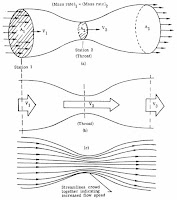
The venturi flow meter takes advantage of the velocity- pressure relationship when a section of pipe gently converges to a small-diameter area (called a throat) before diverging back to the full pipe diameter. The benefit of the venturi flow meter over the orifice flow meter lies in the reduced pressure loss experienced by the fluid.

Annubar Flow Meter
The annubar flow meter (a variation of the simple pitot tube) also takes advantage of the velocity-pressure relationship of flowing fluids. The device causing the change in pressure is a pipe inserted into the natural gas flow.


VELOCITY


There are multiple types of velocity meters: turbine flow meter, vortex-shedding flow meter, and fluid oscillation flow meter. Velocity meters determine fluid flow by measuring a representation of the flow directly. Because the fluid’s velocity is measured (i.e., not the square-root relationship to determine velocity as with differential pressure meters), velocity meters can have better accuracy and usually have better turndown ratios than other meter types.

Turbine Flow Meter
A multi-blade impellor-like device is located in, and horizontal to, the fluid stream in a turbine flow meter. As the fluid passes through the turbine blades, the impellor rotates at a speed related to the fluid’s velocity. Blade speed can be sensed by a number of techniques including magnetic pick-up, mechanical gears, and photocell. The pulses generated as a result of blade rotation are directly proportional to fluid velocity, and hence flow rate.

Vortex-Shedding Flow Meter
A vortex-shedding flow meter senses flow disturbances around a stationary body (called a bluff body) positioned in the middle of the fluid stream. As fluid flows around the bluff body, eddies or vortices are created downstream; the frequencies of these vortices are directly proportional to the fluid velocity.

Fluid Oscillation Flow Meter
A fluid oscillation flow meter uses sensor technology to detect gas oscillations, which corresponds to the flow rate through the meters internal throat design.

For more information on any flow measurement requirement, visit Thompson Equipment (TECO) at http://www.teco-inc.com or call 800-528-8997 for immediate service,

Measuring Flow Using Differential Pressure

Bernoulli's principle
There are several types of flow instruments that rely on the Bernoulli's principle (an increase in the speed of a fluid occurs simultaneously with a decrease in pressure), that measure the differential pressure across the high pressure side and low pressure side of a constriction.

Many industrial processes adapt this principle and measure the differential pressure across an orifice plate or a Venturi tube to measure and control flow.

An orifice plate is a plate with a hole through it. When placed in the pipe, it constricts the flow and provides a pressure differential across the constriction which can be correlated to the flow rate.

A Venturi tube constricts the flow in the same fashion, but instead a plate with a hole, it uses a pipe or tube with a reduced inner diameter to create the flow differential.

This video provides an excellent basic understanding of how this is accomplished. For more information on any type of industrial flow measuring device, visit the TECO website o call 800-528-8997.

NIST Certification of Flow Instrument Calibration and ISO/IEC 17025 Accreditation

The Thompson Equipment Co., Inc., (TECO) facility is used for performing flow calibration for magnetic flow meters as well as other primary liquid flow measuring devices. It is equipped with both mass and volumetric transfer standards.

The output of a customer owned meter is correlated with the output of a standard volumetric meter over a range of its flow capabilities. Each six months, each volumetric standard meter is calibrated against a mass standard. Each year the mass standards are calibrated against the Louisiana Department of Agriculture Standards Laboratory. 

Also on a periodic basis, standards owned by the LA Dept. of Agriculture are calibrated against the National Institute of Standards and Technology (NIST) Each standard device carries with it the appropriate certificate identifying when its last calibration was performed, and by ID number, which standard device it was calibrated against. 

The NIST Traceable Calibration Certificate from TECO documents this trail of calibration so that the calibration of any flow meter can be confirmed all the way back to the NIST Laboratories as is often required by regulatory agencies, ISO-9000 procedures, etc. This provides the user with a high level of confidence in the readings from his instrument.

ISO/IEC 17025 Accredited


TECO's calibration lab is also ISO/IEC 17025 Accredited, meaning it is in accordance with the recognized International Standard ISO/IEC 17025:2005 General requirements for the competence of testing and calibration laboratories. The TECO laboratory also meets any additional program requirements in the field of calibration. This accreditation demonstrates technical competence for a defined scope and the operation of a laboratory quality management system.

Unlike many calibration houses can only verify calibration within the manufacturer's specifications, TECO can provide a wide range of fully accredited flow calibration services to meet virtually any need.

For more information, contact TECO at 800-528-8997 or visit http://teco-inc.com.

Introduction to Industrial Flowmeters

Magmeter
Magnetic flowmeter
(courtesy of Badger Meter)
Flowmeters measure the rate or quantity of moving fluids, in most cases liquid or gas, in an open channel or closed conduit. There are two basic flow measuring systems: those which produce volumetric flow measurements and those delivering a weight or mass based measurement. These two systems, required in many industries such as power, chemical, and water, can be integrated into existing or new installations. For successful integration, the flow measurement systems can be installed in one of several methods, depending upon the technology employed by the instrument. For inline installation, fittings that create upstream and downstream connections that allow for flowmeter installation as an integral part of the piping system. Another configuration, direct insertion, will have a probe or assembly that extends into the piping cross section. There are also non-contact instruments that clamp on the exterior surface of the piping add gather measurements through the pipe wall without any contact with the flowing media.
Turbine flowmeter
Turbine flowmeter
(courtesy of Badger Meter)

Because they are needed for a variety of uses and industries, there are multiple types of flowmeters classified generally into four main groups: mechanical, inferential, electrical, and other.

Quantity meters, more commonly known as positive displacement meters, mass flowmeters, and fixed restriction variable head type flowmeters all fall beneath the mechanical category. Fixed restriction variable head type flowmeters use different sensors and tubes, such as orifice plates, flow nozzles, and venturi and pitot tubes.
Rotameter
Variable area flowmeter
(courtesy of ABB)

Inferential flowmeters include turbine and target flowmeters, as well as variable area flowmeters also known as rotameters.

Laser doppler anemometers, ultrasonic flowmeters, and electromagnetic flowmeters are all electrical-type flowmeters.

Variable Area Flowmeters (Rotameters)

Rotameter
ABB Rotameter
Variable area flowmeters (rotameters) are the most cost effective solution for almost all applications involving the measurement of industrial process liquids, gases or steam.

They meet the application requirements by featuring a wide range of design varieties and sizes. Technology proven, they offer a long life and high reproducibility. Variable area flowmeters are excellent mechanical back-up meters because no external power supply is needed.

TECO was the first firm to represent and sell the Fischer & Porter Rotameter Line, dating back to March, 1947.  With over 70 years of ABB Rotameter history, TECO is your best source to help with your rotameter applications.   http://www.teco-inc.com | 800-528-8997.

An Introduction to Ultrasonic Flow Technology

How Ultrasonic energy is used to measure flow
How Ultrasonic energy
is used to measure flow.
Ultrasonic energy flow meters measure, via sound waves, the velocity of liquid flowing through a pipe––however, this pipe includes not just the traditional “pipe” but also mass flow chutes or something with open channels, free surfaces.

There are three different types of ultrasonic energy measuring tools, called flow meters: the first is the Open Channel flow meter which receives its calculations by computing geometrical distance; the second is the Doppler shift flow meter which reflects ultrasonic beams off sonically reflective materials, e.g. air bubbles; the third is the contrapropogating transit-time flow meter or, more recognizably, the transmission flow meter. The transmission flow meter has two versions: the in-line and the clamp-on. The former is “intrusive” whereas the latter is not, an outward device. These 72+ inch tools, using ultrasound technology, have the ability to measure fluids in bulk, all with distinct properties and principles., The use of this technology is most used in the respective oil and nuclear industries, wastewater technologies, pharmaceutical applications, and the food and beverage industry.

For intrusive flow meters, sensors are fitted opposite one another and alternate bouncing ultrasonic signals back and forth in the pipe, in an almost tennis-like format. In an elementary explanation, by increasing the number of sensors, engineers are able to decipher flow proportions through calculations of velocity between sensory transmissions; thereby, the flow volume can be computed.

For unintrusive flow meters, a literal clamp-on flow meter is placed atop the pipe so as not to interrupt flow. One of the most special properties uninstrusive flow meters offer is the ability to bounce ultrasonic sensors through piping up to four meters in diameter; this makes seemingly impossible feats possible, especially in otherwise difficult fields, e.g. hydroelectric.

Although the technology is pervasive, there are disadvantages still as there are advantages. However, the majority of the equipment’s disadvantages are unavoidable, such as costs and apparatus sensitivities. Nonetheless, there is also the threat of low ultrasonic accuracy, or attenuation, dependent on what systems are used and under what circumstances and command. Alternatively, one of the most publicized advantages is that ultrasonic energy flow technology is used for custody transfer of natural gases and petroleum liquids. Custody transfer usually entails following industry, national, and government standards and regulations. Ultrasonic energy flowmeters and analyzers are also relatively low maintenance, e.g. self-diagnosing. The technology has the capability to control and manage high pressures as well as high temperatures, and, being a popular application among engineers, manufacturers and the like, is reliable in its performance and consistency.

For more information on any industrial flow application, contact TECO at 800-528-8997 or visit www.teco-inc.com.