Showing posts with label flow measurement. Show all posts

Magnetic Flowmeters for Fracing

Fracing
Fracing illustration (USGS)
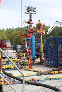
Hydraulic fracturing, or fracing, is the process of exploiting small fissures or cracks in rock layers deep under the earths surface, and increasing their number and size for the purpose of freeing up trapped natural gas. The process includes drilling horizontally in the bedrock and then forcing "frac fluid" into those cracks under very high pressure. The fracturing fluid is made up of water, a special type of sand (referred to as the proppant) and a mixture of chemicals.

Flow measurement is very important in fracing and requires instrumentation with long life and high accuracy.  Frac fluid is a very nasty slurry and it's flow measurement is challenging. Flow instruments are exposed to high pressures, erosive materials and corrosive chemicals.

FracingFrac sand is very erosive and the high pressure and corrosive chemicals complicate things exponentially. Any flowmeter used in fracing applications must not only be rugged enough to withstand these harsh conditions, but the flowmeter must also provide the accuracy required for reliable data reporting to supervisory agencies. Cost-effectively meeting accuracy and longevity requirements for these applications can be frustrating.

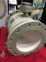
Magnetic flowmeters have always appealed to the fracing industry because of their unfettered flow path, availability of sizes and level of accuracy. Their downfall is their longevity. Standard, off-the-shelf magnetic flowmeters don't last in this environment and can't be considered an economically viable choice.

An excellent solution that provides all the the virtues of magnetic flowmeters, and overcomes the longevity and economics issues, are specialized magnetic flowmeters. Referred to as "severe service flowmeters" or "slurry flowmeters", they are designed with components matched specifically to withstand the mechanical and chemical abuse they will see.

Magnetic flowmeters, specialized for fracing, provide all of a "magmeters" desirable features with these critical enhancements:
  1. A ceramic sleeved liner made of magnesia partially stabilized zirconia. This ceramic can handle the abrasion and chemical attack with very little degradation.
  2. Highly polished, ultra-smooth Tungsten electrodes. The Tungsten provides outstanding wear resistance while the high-polish reduces electrical noise introduced in the electrode circuitry.
  3. Special coatings, or paints, to provide exterior protection.
Fracing flowmeterBy specifying magnetic flowmeters, specialized for fracing, not only do operators save money through increased uptime and decreased health, safety and environmental risk, but also through reduced costs related to flowmeter purchase and repair.

For more information on fracing magnetic flowmeters, contact Thompson Equipment Company (TECO) by calling 800-528-8997 or visit https://teco-inc.com

Important Flowmeter Performance Metrics

Animation of differential flow
Common to most flowmeters are rated levels of performance; some of the more universal
performance metrics include accuracy, precision/repeatability, turndown ratio, resolution, ease of installation, straight pipe run requirements, on-going operations and maintenance, and costs.

Accuracy
Accuracy is the difference between a measured value and the actual value. No flowmeter is 100% accurate and most manufacturers provide a range of accuracies in their product line - tighter accuracy requirements are typically more expensive and may also be more restrictive to specific applications.

Precision/Repeatability
The precision or repeatability of a measurement entails the ability to reproduce the same value (e.g., flow rate) with multiple measurements of the same parameter, under the same conditions.

Turndown Ratio
Rotameter
Rotameter
(ABB)
The turndown ratio refers to the flow rates over which a meter will maintain a certain accuracy and repeatability. For example, a steam flow meter that can measure accurately from 1,000 pounds per hour (pph) to 25,000 pph has a turndown ratio of 25:1. The larger the turndown ratio, the greater the range over which the meter can measure the parameter within the accuracy stated.

Resolution
The resolution is the smallest increment of flow that can be incrementally registered by the meter. For example, a water meter designed for a small diameter pipe may be able to provide a resolution of 100 pulses per gallon (or more) as a signal output, but a meter designed for a larger pipe or higher maximum flow may only be able to provide 1 pulse per 100 gallons. Further, a very large flow meter may only be able to provide 1 pulse per 1000 gallons. The metering system may have limitations with regard to peak signal frequency or minimum time between pulses to properly register the data signal.

Ease of Installation
Select make-and-model decisions considering size and weight constraints, specific electrical and communications needs, and the overall environment the flowmeter will operate in.

Magmeter
Magnetic flowmeter
(TECO)
Straight-pipe Run Requirements
Applicable to some types of fluid (gas, liquid and steam) flowmeters, straight-pipe run requirements relate to the length of unobstructed straight pipe required leading up to and immediately following the flow meter’s location. Obstructions in the fluid flow (such as elbows, tees, filters, valves, and sensor fittings) cause changes in the flow pattern (flow regime and velocity profile). Straight-pipe runs allow the flow pattern to normalize/stabilize making measurements by velocity-type and differential-pressure-type flow meters less prone to measurement error. Straight-pipe run requirements are usually expressed in terms of the number of pipe diameters.

The straight pipe requirement is in addition to the length of the flowmeter itself. The straight-pipe run requirements can be reduced with the addition of flow straightening or flow conditioning devices installed upstream.

Ongoing Operations and Maintenance
Vortex flowmeter
Vortex flowmeter
(ABB)
The lowest cost flow metering technology may not be the best choice if it has high associated maintenance costs (e.g., frequent service, calibration and recalibration, sensor replacement). As with most capital purchases, a life-cycle cost approach (including all capital and recurring costs) is recommended for decision making.

Installation Versus Capital Cost
In some situations, the cost to install a flowmeter can be greater than the capital cost; this can be true where system shutdowns are necessary for flowmeter installations, or where significant redesign efforts are needed to accommodate a flowmeter’s physical size, weight, or required connection. In these cases, decision makers should consider alternative technologies that may have a higher capital cost but a much lower installed cost. A good example of this is the use of non-intrusive flow metering technologies (e.g., ultrasonic flowmeters) that typically have a high capital cost but often a significantly reduced installed cost. It is recommended that meters be installed with isolation valves or switches making it easier to remove, replace, or service the meter in the future.

Reprinted and abstracted from US Department of Energy paper titled "Metering Best Practices: A Guide to Achieving Utility Resource Efficiency, "

What Are Orifice Plates?

Fig. 1 - Orifice Plates
The orifice plate is the simplest of the flowpath restrictions used in flow detection, as well as the most economical. Orifice plates are flat plates 1/16 to 1/4 inch thick. They are normally mounted between a pair of flanges and are installed in a straight run of smooth pipe to avoid disturbance of flow patterns from fittings and valves.

Three kinds of orifice plates are used: concentric, eccentric, and segmental (as shown in Figure 1).

The concentric orifice plate is the most common of the three types. As shown, the orifice is equidistant (concentric) to the inside diameter of the pipe. Flow through a sharp-edged orifice plate is characterized by a change in velocity. As the fluid passes through the orifice, the fluid converges, and the velocity of the fluid increases to a maximum value. At this point, the pressure is at a minimum value. As the fluid diverges to fill the entire pipe area, the velocity decreases back to the original value. The pressure increases to about 60% to 80% of the original input value. The pressure loss is irrecoverable; therefore, the output pressure will always be less than the input pressure. The pressures on both sides of the orifice are measured, resulting in a differential pressure which is proportional to the flow rate.

Segmental and eccentric orifice plates are functionally identical to the concentric orifice. The circular section of the segmental orifice is concentric with the pipe. The segmental portion of the orifice eliminates damming of foreign materials on the upstream side of the orifice when mounted in a horizontal pipe. Depending on the type of fluid, the segmental section is placed on either the top or bottom of the horizontal pipe to increase the accuracy of the measurement.

Eccentric orifice plates shift the edge of the orifice to the inside of the pipe wall. This design also prevents upstream damming and is used in the same way as the segmental orifice plate.
Orifice plates have two distinct disadvantages; they cause a high permanent pressure drop (outlet pressure will be 60% to 80% of inlet pressure), and they are subject to erosion, which will eventually cause inaccuracies in the measured differential pressure.

Contact TECO with any process flow question or requirement. You can find them by visiting https://teco-inc.com or by calling (504) 833-6381.

Water Flow Metering and Measurement

water flow measurement devices
Water flow measurement device comparison (click for larger view)
Water is commonly measured and sold in volumetric measurements, which allows for lower-cost metering options. The specific measurement technology chosen will depend on a number of factors including, but not limited to, current design, budget, accuracy requirements, resolution, minimum flow rate, potable versus non-potable (or at least filtered versus non-filtered water), range of flow rates, and maximum flow rate.

Volumetric water measurement can be broken down into three general operating designs:
  • Positive displacement
  • Differential pressure
  • Velocity

Positive Displacement – Nutating-Disk Flow Meter

Nutating-disk flow meters are the most common meter technology used by water utilities to measure potable-water consumption for service connections up to 3-inch. The nutating-disk flow meter consists of a disk mounted on a spherically shaped head and housed in a measuring chamber. As the fluid flows through the meter passing on either side of the disk, it imparts a rocking or nutating motion to the disk. This motion is then transferred to a shaft mounted perpendicular to the disk. It is this shaft that traces out a circular motion – transferring this action to a register that records flow.

There are a variety of differential pressure devices useful for water metering; two of the more common devices include orifice flow meters and venturi flow meters.

Differential Pressure – Orifice Flow Meter

The orifice element is typically a thin, circular metal disk held between two flanges in the fluid stream. The center of the disk is formed with a specific-size and shape hole, depending on the expected fluid flow parameters (e.g., pressure and flow range). As the fluid flows through the orifice, the restriction creates a pressure differential upstream and downstream of the orifice proportional to the fluid flow rate. This differential pressure is measured and a flow rate calculated based on the differential pressure and fluid properties.

Differential Pressure – Venturi Flow Meter

The venturi flow meter takes advantage of the velocity-pressure relationship when a section of pipe gently converges to a small-diameter area (called a throat) before diverging back to the full pipe diameter. The benefit of the venturi flow meter over the orifice flow meter lies in the reduced pressure loss experienced by the fluid.

The velocity measurement technologies described in this section include the turbine flow meter, vortex-shedding flow meter, and ultrasonic flow meters.

Velocity – Turbine Flow Meter

A multi-blade impellor-like device is located in, and horizontal to, the fluid stream in a turbine flow meter. As the fluid passes through the turbine blades, the impellor rotates at a speed related to the fluid’s velocity. Blade speed can be sensed by a number of techniques including magnetic pick-up, mechanical gears, and photocell. The pulses generated as a result of blade rotation are directly proportional to fluid velocity, and hence flow rate.

Velocity – Vortex-Shedding Flow Meter

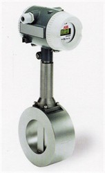
A vortex-shedding flow meter senses flow disturbances around a stationary body (called a bluff body) positioned in the middle of the fluid stream. As fluid flows around the bluff body, eddies or vortices are created downstream; the frequencies of these vortices are directly proportional to the fluid velocity.

Velocity – Ultrasonic Flow Meters

There are two different types of ultrasonic flow meters, transit-time and Doppler-effect. The two technologies use ultrasonic signals very differently to determine fluid flow and are best applied to different fluid applications. Transit-time ultrasonic flow meters require the use of two signal transducers. Each transducer includes both a transmitter and a receiver function. As fluid moves through the system, the first transducer sends a signal and the second receives it. The process is then reversed. Upstream and downstream time measurements are compared. With flow, sound will travel faster in the direction of flow and slower against the flow. Transit-time flow meters are designed for use with clean fluids, such as water.

Doppler-effect ultrasonic flow meters use a single transducer. The transducer has both a transmitter and receiver. The high-frequency signal is sent into the fluid. Doppler-effect flow meters use the principal that sound waves will be returned to a transmitter at an altered frequency if reflectors in the liquid are in motion. This frequency shift is in direct proportion to the velocity of the liquid. The echoed sound is precisely measured by the instrument to calculate the fluid flow rate.

Because the ultrasonic signal must pass through the fluid to a receiving transducer, the fluid must not contain a significant concentration of bubbles or solids. Otherwise the high frequency sound will be attenuated and too weak to traverse the distance to the receiver. Doppler-effect ultrasonic flow meters require that the liquid contain impurities, such as gas bubbles or solids, for the Doppler-effect measurement to work. One of the most attractive aspects of ultrasonic flow meters is they are non-intrusive to the fluid flow. An ultrasonic flow meter can be externally mounted to the pipe and can be used for both temporary and permanent metering.

For more information on any flow application, visit http://www.teco-inc.com or call (504) 833-6381.


Natural Gas Flow Metering and Measurement


Natural gas is a hydrocarbon gas mixture consisting primarily methane, but includes a host of other chemical components. Accurate natural gas flow measurement usually requires the measurement of the fluid’s temperature and pressure in addition to flow. Additional constraints on natural gas measurement may include the physical space available or possibly configuration and weight of the metering system. Some of the fluid metering technologies require specific lengths of pipe, both upstream and downstream of the meter for proper function.

Before any technology decisions are made, discussions with equipment vendors and/or design engineers are recommended to ensure proper technology selection and installation design.

Depending on the application, flow rate, installation access, and desired accuracy, there are a number of technology options for natural gas metering. In general, measurement of natural gas volumetric flow rate is represented in standard cubic feet per hour (scfh) or per minute (scfm). The actual mass of gas flowing past a point of measurement changes with its temperature and pressure. Density changes resulting from temperature and pressure differences can result in differences between the energy content of similar volumes of the gas. To equalize the effect of density variations when metering gas, conditions are referenced against standard temperature and pressure conditions, hence standard cubic feet (scf) instead of actual cubic feet (acf). Gas flowmeters must compensate for density differences between standard conditions and actual conditions to accurately define standard flow rates.

The most common volumetric gas metering devices fall into one of the following categories:
  • Positive displacement
  • Differential pressure
  • Velocity 
In most applications, gas flowmeters are installed downstream of pressure regulation devices and the meters are then calibrated to that pressure. Natural gas meters may include options for temperature and pressure compensation.


POSITIVE DISPLACEMENT


A positive displacement meter functions by the fluid physically displacing the measuring mechanism and this displacement becomes the metered value. Of relevancy to natural gas measurement, the two predominant technologies are the diaphragm meter (most common) and the rotary meter. In each case, the volume of gas for measurement physically impinges on a measuring element (flexible diaphragm or rotary blower) to increment a recording dial or other output. The primary advantage of positive displacement flow meters is there are no straight-run piping requirements to establish a flow pattern that can be accurately metered. The primary disadvantage of positive displacement meters is higher pressure drops experienced across the meter at peak flow rates.


DIFFERENTIAL PRESSURE


There are multiple types of differential pressure meters: orifice flow meter, venture flow meter, and annubar flow meter. All differential pressure meters rely on the velocity-pressure relationship of flowing fluids for operation.

Orifice Flow Meter 
The orifice element is typically a thin, circular metal disk held between two flanges in the fluid stream. The center of the disk is formed with a specific-size and shape hole, depending on the expected fluid flow parameters (e.g., pressure and flow range). As the fluid flows through the orifice, the restriction creates a pressure differential upstream and downstream of the orifice proportional to the fluid flow rate. This differential pressure is measured and a flow rate calculated based on the differential pressure and fluid properties.

Venturi Flow Meter
The venturi flow meter takes advantage of the velocity- pressure relationship when a section of pipe gently converges to a small-diameter area (called a throat) before diverging back to the full pipe diameter. The benefit of the venturi flow meter over the orifice flow meter lies in the reduced pressure loss experienced by the fluid.

Annubar Flow Meter
The annubar flow meter (a variation of the simple pitot tube) also takes advantage of the velocity-pressure relationship of flowing fluids. The device causing the change in pressure is a pipe inserted into the natural gas flow.


VELOCITY


There are multiple types of velocity meters: turbine flow meter, vortex-shedding flow meter, and fluid oscillation flow meter. Velocity meters determine fluid flow by measuring a representation of the flow directly. Because the fluid’s velocity is measured (i.e., not the square-root relationship to determine velocity as with differential pressure meters), velocity meters can have better accuracy and usually have better turndown ratios than other meter types.

Turbine Flow Meter
A multi-blade impellor-like device is located in, and horizontal to, the fluid stream in a turbine flow meter. As the fluid passes through the turbine blades, the impellor rotates at a speed related to the fluid’s velocity. Blade speed can be sensed by a number of techniques including magnetic pick-up, mechanical gears, and photocell. The pulses generated as a result of blade rotation are directly proportional to fluid velocity, and hence flow rate.

Vortex-Shedding Flow Meter
A vortex-shedding flow meter senses flow disturbances around a stationary body (called a bluff body) positioned in the middle of the fluid stream. As fluid flows around the bluff body, eddies or vortices are created downstream; the frequencies of these vortices are directly proportional to the fluid velocity.

Fluid Oscillation Flow Meter
A fluid oscillation flow meter uses sensor technology to detect gas oscillations, which corresponds to the flow rate through the meters internal throat design.

For more information on any flow measurement requirement, visit Thompson Equipment (TECO) at http://www.teco-inc.com or call 800-528-8997 for immediate service,

Understanding Coriolis Flow Measurement

Thompson Equipment
Coriolis flowmeters directly measure the mass flow of a subject fluid, which is inclusive of regular and supercritical liquids and liquefied gases. Operating on the Coriolis effect principle, Coriolis flowmeters create a controlled condition in which the mass flow of the fluid can be directly measured. They rely on motion mechanics: one or two tubes are aligned inside a Coriolis flowmeter, then made to oscillate with an exciter. Fluid flows through the oscillating tubes, twisting them slightly in proportion to the mass flow of the fluid and its inertia. There are highly reactive sensors attached to the tubes; when the measured substance flows through the vibrating tubes, the numeric difference between sensor readings provide the basis of the resulting fluid is mass flow measurement. This process also delivers a second measurement: the density of the substance. The sensors measure the frequency of oscillations. Coriolis flowmeters rely on direct computation instead of an algorithm, and therefore are regarded as highly accurate instruments in industry, coming in at 0.1 percent accuracy in some cases.
Coriolis principles
Rotation without mass flow
(image courtesy of Wikipedia).
Coriolis principles
Rotation with mass flow
(image courtesy of Wikipedia).
Coriolis flowmeters are advantageous choices for many industrial applications. They are used to measure drinking water, oils and gases, chemicals, etc. However, these mass flow measurement products particularly stand out in the chemical industry. As a prerequisite for most fluid processing operations, measurements and quantities often rely upon mass instead of upon volume. Coriolis flowmeters, with their direct measurement of mass flow, can be the optimal choice for applications requiring mass flow measurement.

As beneficial as Coriolis flowmeters are, they are not immune to some engineering and practical limitations. The most recognized limitation is the size of the pipes the meters are able to accommodate. A Coriolis meter is comparatively large, when other measurement instrument technologies are considered, making it difficult to place in some installations. In addition to being recognized as one of the most accurate flow measuring technologies, the Coriolis flowmeter requires little maintenance.
Coriolis principles
The vibration pattern with mass flow
(image courtesy of Wikipedia).
The vibration pattern during no-flow
(image courtesy of Wikipedia).

Selecting and configuring the instrument properly and assuring that installation is performed in accordance with manufacturer instructions are necessary tasks to achieving best instrument performance. Reach out to an instrumentation specialist with your flow measurement challenges, combining your process knowledge with their product application expertise to develop effective solutions.

For additional information on any industrial flow measuring technologies visit Thompson Equipment (TECO) at  http://www.teco-inc.com or call 800-528-8997.