This “Handbook for Variable Area Flowmeters“, courtesy of ABB and Thompson Equipment, is a practical guide for the user with selection criteria for real applications (see Check List/Parameter Questionnaire), correction factors, Accuracy Classes, corrosion resistance tables and much more. A separate flyer with actual pictures demonstrate the application versatility.
Answers are provided to frequently asked questions about this measurement principle (see Page 20) and we have incorporated a preferential quick ship program for the most popular instrument versions.
We hope that this Handbook provides you with a practical selection guide; naturally our sales team is always ready to provide you with any personal assistance you may require.
Thompson Equipment (TECO)
800-528-8997
https://teco-inc.com
Providing educational information on flowmeters, industrial control, process instrumentation, valves, and valve automation. Posts include interesting and unique industrial control applications, new product information, and ways of improving efficiency and saving money through proper maintenance, repair, service, and re-manufacturing.
Courtesy of Thompson Equipment Company | TECO-INC.COM | (504) 833-6381
Showing posts with label flow control. Show all posts
Showing posts with label flow control. Show all posts
The Role of the High and Low Pressure Ports on a Differential Pressure Transmitter
http://www.teco-inc.com
800-528-8997
Differential Pressure Flow Metering for the Chemical Processing Industry White Paper
 Flow measurement is a critical aspect of plant operation in the Chemical Processing Industry (CPI). Users choosing equipment to meter the flow of liquid or gas processes must consider a wide range of factors to arrive at an optimal solution Experience has shown there are significant differences between meter technologies, with each type of device having its own advantages and disadvantages for processing facilities
Common Differential Flow Metering Methods:
- Venturi
- Cone Meter
- Wedge Meter
- Averaging Pitot Tube
Badger Meter, a premier manufacturer of industrial flow meters, has authored an excellent white paper explaining the use of differential pressure flow metering in the chemical processing industry. You can get the white paper at this link.
For more information, visit Thompson Equipment Company (TECO) at https://teco-inc.com or call 800-528-8997 for immediate service.
Important Flowmeter Performance Metrics
 |
| Animation of differential flow |
performance metrics include accuracy, precision/repeatability, turndown ratio, resolution, ease of installation, straight pipe run requirements, on-going operations and maintenance, and costs.
Accuracy
Accuracy is the difference between a measured value and the actual value. No flowmeter is 100% accurate and most manufacturers provide a range of accuracies in their product line - tighter accuracy requirements are typically more expensive and may also be more restrictive to specific applications.
Precision/Repeatability
The precision or repeatability of a measurement entails the ability to reproduce the same value (e.g., flow rate) with multiple measurements of the same parameter, under the same conditions.
Turndown Ratio
 |
| Rotameter (ABB) |
Resolution
The resolution is the smallest increment of flow that can be incrementally registered by the meter. For example, a water meter designed for a small diameter pipe may be able to provide a resolution of 100 pulses per gallon (or more) as a signal output, but a meter designed for a larger pipe or higher maximum flow may only be able to provide 1 pulse per 100 gallons. Further, a very large flow meter may only be able to provide 1 pulse per 1000 gallons. The metering system may have limitations with regard to peak signal frequency or minimum time between pulses to properly register the data signal.
Ease of Installation
Select make-and-model decisions considering size and weight constraints, specific electrical and communications needs, and the overall environment the flowmeter will operate in.
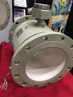 |
| Magnetic flowmeter (TECO) |
Applicable to some types of fluid (gas, liquid and steam) flowmeters, straight-pipe run requirements relate to the length of unobstructed straight pipe required leading up to and immediately following the flow meter’s location. Obstructions in the fluid flow (such as elbows, tees, filters, valves, and sensor fittings) cause changes in the flow pattern (flow regime and velocity profile). Straight-pipe runs allow the flow pattern to normalize/stabilize making measurements by velocity-type and differential-pressure-type flow meters less prone to measurement error. Straight-pipe run requirements are usually expressed in terms of the number of pipe diameters.
The straight pipe requirement is in addition to the length of the flowmeter itself. The straight-pipe run requirements can be reduced with the addition of flow straightening or flow conditioning devices installed upstream.
Ongoing Operations and Maintenance
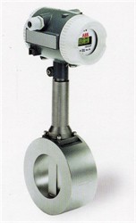 |
| Vortex flowmeter (ABB) |
Installation Versus Capital Cost
In some situations, the cost to install a flowmeter can be greater than the capital cost; this can be true where system shutdowns are necessary for flowmeter installations, or where significant redesign efforts are needed to accommodate a flowmeter’s physical size, weight, or required connection. In these cases, decision makers should consider alternative technologies that may have a higher capital cost but a much lower installed cost. A good example of this is the use of non-intrusive flow metering technologies (e.g., ultrasonic flowmeters) that typically have a high capital cost but often a significantly reduced installed cost. It is recommended that meters be installed with isolation valves or switches making it easier to remove, replace, or service the meter in the future.
Reprinted and abstracted from US Department of Energy paper titled "Metering Best Practices: A Guide to Achieving Utility Resource Efficiency, "
What Are Rotameters?
 |
| Rotameter (ABB) |
The rotameter has a number of advantages for use in a process. No external power or fuel is required, only the corresponding flow and gravity. They are simple devices that can be produced from low-cost materials, which is a main reason for the rotameter’s widespread use across many applications. Additionally, the area of the flow passage increases when the float moves, resulting in a linear relationship. The clear glass used also allows for a low risk of thermal shock and resulting issues from measuring chemicals. Rotameters also typically do not experience large drops in pressure, are simple to install, and are repeatable for long periods of time as long as they are operating under the same process conditions.
A few limitations exist in rotameters, the first of which relates to the fact the rotameter relies on displacement to function. A rotameter made to measure a certain substance at a particular temperature is only going to be accurate when measuring the substance and process qualities originally intended. While a rotameter can be scaled to measure different densities and viscosities, a limitation exists when the fluid characteristics being measured change in complexity. Secondly, while floats are often designed to function independent of viscosity, it can be difficult to ensure their effectiveness. Additionally, measurements being evaluated via rotameters can be uncertain when the float oscillates or near the bottom of the scale being used by the rotameter.
Certain fluids may also obscure the reading on the rotameter since the reading must be read through the flowing medium. This limitation can be countered by coupling he rotameter with a transducer in certain process applications. Another option for readability involves using a magnetic float that can be accompanied by a follower outside the tube, allowing the operator to easily read the measurement.
For more information about rotameters, visit https://teco-inc.com/ABB.
What Are Vortex Shedding Flowmeters?
 |
| Vortex Shedding Flowmeter (ABB) |
Vortex shedding flowmeters are a type of flowmeter available to the process industry for the consistent evaluation of flow rates. These flowmeters measure the volumetric flow rate of media such as steam flowing in pipes, gases, and low viscosity liquids, boasting both versatility and dependability. Since they have no moving parts, they are virtually impervious to wear.
 |
| Animation of vortex creation (Cesareo de La Rosa Siqueira via Wikipedia) |
Principles of Operation
 |
| Photograph of vortices (credit Jürgen Wagner via Wikipedia) |
A "shedder" bar (also known as a bluff body) in the path of the flowing fluid produces flow disturbances called vortices. The resulting vortex trail is predictable and proportional to the fluid flow rate. This phenomena is know as the "Von Kármán vortex street" (see illustrations to the right). Sensitive electronic sensors downstream of the shedder bar measures the frequency of the vortices and produce a small electrical pulse with every vortex created. The electrical pulses also also proportional to fluid velocity and is the basis for calculating a volumetric flow rate, using the cross sectional area of the flow measuring device.
Typical Areas of Use
Vortex shedding flowmeters are used on steam, cryogenic liquids, hydrocarbons, air, feed water, and industrial gases.
Applications to Avoid
Splitting higher viscosity fluids into concordant vertices is extremely difficult due to the internal friction present, so using vortex shedding flowmeters on high viscosity media should be avoided. Also, avoid applications with low flow rates and low Reynolds Numbers, as the vortices created are unstable.
Consideration for Use
Consideration must be given to applications with low Reynolds numbers, as the generation of vortices declines at critical points of reduced velocity. Low pressure can also be a problem in this regard. Users must take Reynolds number, velocity, and density into consideration before choosing a vortex shedding flow meter. As always, it's best to discuss your application with an knowledgable support professional before specifying, purchasing, or installing this type of flowmeter.
Understanding Why Cavitation and Flashing are Bad for Control Valves and Pumps
 |
| Cavitation is caused by bubbles collapsing asymmetrically at very high speeds, producing extremely high pressures in very small areas. |
If fluid being throttled is a liquid, and the pressure at the vena contracta is less than the vapor pressure of that liquid at the flowing temperature, the liquid will spontaneously boil. This is the phenomenon of flashing. If, however, the pressure recovers to a point greater than the vapor pressure of the liquid, the vapor will re-condense back into liquid again. This is called cavitation.
As destructive as flashing is to a control valve, cavitation is worse. When vapor bubbles re-condense into liquid they often do so asymmetrically, one side of the bubble collapsing before the rest of the bubble. This has the effect of translating the kinetic energy of the bubble’s collapse into a high-speed “jet” of liquid in the direction of the asymmetrical collapse. These liquid “microjets” have been experimentally measured at speeds up to 100 meters per second (over 320 feet per second). What is more, the pressure applied to the surface of control valve components in the path of these microjets is intense. Each microjet strikes the valve component surface over a very small surface area, resulting in a very high pressure (P = F/A ) applied to that small area. Pressure estimates as high as 1500 newtons per square millimeter (1.5 giga-pascals, or about 220000 PSI!) have been calculated for cavitating control valve applications involving water.
Watch the video below to better understand the impact of cavitation on a process flow system.
Industrial Valve Basics: Rotary Ball Valves
 |
Cut-away view of ball
valve components:
1) Body
2) Seat
3) Foating ball
4) Lever handle
5) Stem
(Image courtesy of Wikipedia)
|
Most ball valve actuators are of the quick-acting type, which require a 90° turn of the valve handle to operate the valve. Other ball valve actuators are planetary gear-operated. This type of gearing allows the use of a relatively small handwheel and operating force to operate a fairly large valve.
Some ball valves have been developed with a spherical surface coated plug that is off to one side in the open position and rotates into the flow passage until it blocks the flowpath completely. Seating is accomplished by the eccentric movement of the plug. The valve requires no lubrication and can be used for throttling service.
Advantages
A ball valve is generally the least expensive of any valve configuration and has low maintenance costs. In addition to quick, quarter turn on-off operation, ball valves are compact, require no lubrication, and give tight sealing with low torque.
Disadvantages
Conventional ball valves have relatively poor throttling characteristics. In a throttling position, the partially exposed seat rapidly erodes because of the impingement of high velocity flow.
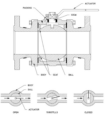 |
| Typical Ball Valve (click for larger view). |
Port Patterns
Ball valves are available in the venturi, reduced, and full port pattern. The full port pattern has a ball with a bore equal to the inside diameter of the pipe.
Valve Materials
Balls are usually metallic in metallic bodies with trim (seats) produced from elastomeric (elastic materials resembling rubber) materials. Plastic construction is also available.
The resilient seats for ball valves are made from various elastomeric material. The most common seat materials are teflon (TFE), filled TFE, Nylon, Buna-N, Neoprene, and combinations of these materials. Because of the elastomeric materials, these valves cannot be used at elevated temperatures. Care must be used in the selection of the seat material to ensure that it is compatible with the materials being handled by the valve.
Ball Valve Stem Design
The stem in a ball valve is not fastened to the ball. It normally has a rectangular portion at the ball end which fits into a slot cut into the ball. The enlargement permits rotation of the ball as the stem is turned.
Ball Valve Bonnet Design
A bonnet cap fastens to the body, which holds the stem assembly and ball in place. Adjustment of the bonnet cap permits compression of the packing, which supplies the stem seal. Packing for ball valve stems is usually in the configuration of die-formed packing rings normally of TFE, TFE-filled, or TFE-impregnated material. Some ball valve stems are sealed by means of O-rings rather than packing.
Ball Valve Position
Some ball valves are equipped with stops that permit only 90° rotation. Others do not have stops and may be rotated 360°. With or without stops, a 90° rotation is all that is required for closing or opening a ball valve.
The handle indicates valve ball position. When the handle lies along the axis of the valve, the valve is open. When the handle lies 90° across the axis of the valve, the valve is closed. Some ball valve stems have a groove cut in the top face of the stem that shows the flowpath through the ball. Observation of the groove position indicates the position of the port through the ball. This feature is particularly advantageous on multiport ball valves.
For more information about any style industrial valve, contact TECO at 800-528-8997 or visit http://www.teco-inc.com.
Steam Flow Metering and Measurement
For steam, energy is primarily contained in the latent heat and, to a lesser extent, the sensible heat of the fluid. The latent heat energy is released as the steam condenses to water. Additional sensible heat energy may be released if the condensate is further lowered in temperature. In steam measuring, the energy content of the steam is a function of the steam mass, temperature and pressure. Even after the steam releases its latent energy, the hot condensate still retains considerable heat energy, which may or may not be recovered (and used) in a constructive manner. The energy manager should become familiar with the entire steam cycle, including both the steam supply and the condensate return.
When compared to other liquid flow measuring, the measuring of steam flow presents one of the most challenging measuring scenarios. Most steam flowmeters measure a velocity or volumetric flow of the steam and, unless this is done carefully, the physical properties of steam will impair the ability to measure and define a mass flow rate accurately.
Steam is a compressible fluid; therefore, a reduction in pressure results in a reduction in density. Temperature and pressure in steam lines are dynamic. Changes in the system’s dynamics, control system operation and instrument calibration can result in considerable differences between actual pressure/temperature and a meter’s design parameters. Accurate steam flow measurement generally requires the measurement of the fluid’s temperature, pressure, and flow. This information is transmitted to an electronic device or flow computer (either internal or external to the flow meter electronics) and the flow rate is corrected (or compensated) based on actual fluid conditions.
The temperatures associated with steam flow measurement are often quite high. These temperatures can affect the accuracy and longevity of measuring electronics. Some measuring technologies use close-tolerance moving parts that can be affected by moisture or impurities in the steam. Improperly designed or installed components can result in steam system leakage and impact plant safety. The erosive nature of poor-quality steam can damage steam flow sensing elements and lead to inaccuracies and/or device failure.
The challenges of measuring steam can be simplified measuring the condensed steam, or condensate. The measuring of condensate (i.e., high-temperature hot water) is an accepted practice, often less expensive and more reliable than steam measuring. Depending on the application, inherent inaccuracies in condensate measuring stem from unaccounted for system steam losses. These losses are often difficult to find and quantify and thus affect condensate measurement accuracy.
Volumetric measuring approaches used in steam measuring can be broken down into two operating designs:
- Differential pressure measurement
- Velocity measuring technologies
DIFFERENTIAL
For steam three differential pressure flowmeters are highlighted: orifice flow meter, annubar flow meter, and spring-loaded variable area flow meter. All differential pressure flowmeters rely on the velocity-pressure relationship of flowing fluids for operation.
Differential Pressure – Orifice Flow Meter
Historically, the orifice flow meter is one of the most commonly used flowmeters to measure steam flow. The orifice flow meter for steam functions identically to that for natural gas flow. For steam measuring, orifice flow flowmeters are commonly used to monitor boiler steam production, amounts of steam delivered to a process or tenant, or in mass balance activities for efficiency calculation or trending.
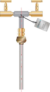 |
| Annular flowmeter (courtesy of Badger Meter) |
Differential Pressure – Annubar Flow Meter
The annubar flow meter (a variation of the simple pitot tube) also takes advantage of the velocity-pressure relationship of flowing fluids. The device causing the change in pressure is a pipe inserted into the steam flow.
Differential Pressure – Spring-Loaded Variable Area Flow Meter
The spring-loaded variable area flow meter is a variation of the rotameter. There are alternative configurations but in general, the flow acts against a spring-mounted float or plug. The float can be shaped to give a linear relationship between differential pressure and flow rate. Another variation of the spring-loaded variable area flow meter is the direct in-line variable area flow meter, which uses a strain gage sensor on the spring rather than using a differential pressure sensor.
VELOCITY
The two main type of velocity flowmeters for steam flow, turbine and vortex shedding, both sense some flow characteristic directly proportional to the fluid’s velocity.
Turbine Flow Meter
A multi-blade impellor-like device is located in, and horizontal to, the fluid stream in a turbine flow meter. As the fluid passes through the turbine blades, the impellor rotates at a speed related to the fluid’s velocity. Blade speed can be sensed by a number of techniques including magnetic pick-up, mechanical gears, and photocell. The pulses generated as a result of blade rotation are directly proportional to fluid velocity, and hence flow rate.
Velocity – Vortex-Shedding Flow Meter
 |
| Vortex flowmeter (courtesy of Badger Meter) |
A vortex-shedding flow meter senses flow disturbances around a stationary body (called a bluff body) positioned in the middle of the fluid stream. As fluid flows around the bluff body, eddies or vortices are created downstream; the frequencies of these vortices are directly proportional to the fluid velocity.
For more information on any flow measurement requirement, visit Thompson Equipment (TECO) at http://www.teco-inc.com or call 800-528-8997 for immediate service,
Understanding Coriolis Flow Measurement
Coriolis flowmeters directly measure the mass flow of a subject fluid, which is inclusive of regular and supercritical liquids and liquefied gases. Operating on the Coriolis effect principle, Coriolis flowmeters create a controlled condition in which the mass flow of the fluid can be directly measured. They rely on motion mechanics: one or two tubes are aligned inside a Coriolis flowmeter, then made to oscillate with an exciter. Fluid flows through the oscillating tubes, twisting them slightly in proportion to the mass flow of the fluid and its inertia. There are highly reactive sensors attached to the tubes; when the measured substance flows through the vibrating tubes, the numeric difference between sensor readings provide the basis of the resulting fluid is mass flow measurement. This process also delivers a second measurement: the density of the substance. The sensors measure the frequency of oscillations. Coriolis flowmeters rely on direct computation instead of an algorithm, and therefore are regarded as highly accurate instruments in industry, coming in at 0.1 percent accuracy in some cases.
Coriolis flowmeters are advantageous choices for many industrial applications. They are used to measure drinking water, oils and gases, chemicals, etc. However, these mass flow measurement products particularly stand out in the chemical industry. As a prerequisite for most fluid processing operations, measurements and quantities often rely upon mass instead of upon volume. Coriolis flowmeters, with their direct measurement of mass flow, can be the optimal choice for applications requiring mass flow measurement.
As beneficial as Coriolis flowmeters are, they are not immune to some engineering and practical limitations. The most recognized limitation is the size of the pipes the meters are able to accommodate. A Coriolis meter is comparatively large, when other measurement instrument technologies are considered, making it difficult to place in some installations. In addition to being recognized as one of the most accurate flow measuring technologies, the Coriolis flowmeter requires little maintenance.
Selecting and configuring the instrument properly and assuring that installation is performed in accordance with manufacturer instructions are necessary tasks to achieving best instrument performance. Reach out to an instrumentation specialist with your flow measurement challenges, combining your process knowledge with their product application expertise to develop effective solutions.
 |
| Rotation without mass flow (image courtesy of Wikipedia). |
 |
| Rotation with mass flow (image courtesy of Wikipedia). |
As beneficial as Coriolis flowmeters are, they are not immune to some engineering and practical limitations. The most recognized limitation is the size of the pipes the meters are able to accommodate. A Coriolis meter is comparatively large, when other measurement instrument technologies are considered, making it difficult to place in some installations. In addition to being recognized as one of the most accurate flow measuring technologies, the Coriolis flowmeter requires little maintenance.
 |
| The vibration pattern with mass flow (image courtesy of Wikipedia). |
 |
| The vibration pattern during no-flow (image courtesy of Wikipedia). |
Selecting and configuring the instrument properly and assuring that installation is performed in accordance with manufacturer instructions are necessary tasks to achieving best instrument performance. Reach out to an instrumentation specialist with your flow measurement challenges, combining your process knowledge with their product application expertise to develop effective solutions.
For additional information on any industrial flow measuring technologies visit Thompson Equipment (TECO) at http://www.teco-inc.com or call 800-528-8997.
An Introduction to Ultrasonic Flow Technology
 |
| How Ultrasonic energy is used to measure flow. |
There are three different types of ultrasonic energy measuring tools, called flow meters: the first is the Open Channel flow meter which receives its calculations by computing geometrical distance; the second is the Doppler shift flow meter which reflects ultrasonic beams off sonically reflective materials, e.g. air bubbles; the third is the contrapropogating transit-time flow meter or, more recognizably, the transmission flow meter. The transmission flow meter has two versions: the in-line and the clamp-on. The former is “intrusive” whereas the latter is not, an outward device. These 72+ inch tools, using ultrasound technology, have the ability to measure fluids in bulk, all with distinct properties and principles., The use of this technology is most used in the respective oil and nuclear industries, wastewater technologies, pharmaceutical applications, and the food and beverage industry.
For intrusive flow meters, sensors are fitted opposite one another and alternate bouncing ultrasonic signals back and forth in the pipe, in an almost tennis-like format. In an elementary explanation, by increasing the number of sensors, engineers are able to decipher flow proportions through calculations of velocity between sensory transmissions; thereby, the flow volume can be computed.
For unintrusive flow meters, a literal clamp-on flow meter is placed atop the pipe so as not to interrupt flow. One of the most special properties uninstrusive flow meters offer is the ability to bounce ultrasonic sensors through piping up to four meters in diameter; this makes seemingly impossible feats possible, especially in otherwise difficult fields, e.g. hydroelectric.
Although the technology is pervasive, there are disadvantages still as there are advantages. However, the majority of the equipment’s disadvantages are unavoidable, such as costs and apparatus sensitivities. Nonetheless, there is also the threat of low ultrasonic accuracy, or attenuation, dependent on what systems are used and under what circumstances and command. Alternatively, one of the most publicized advantages is that ultrasonic energy flow technology is used for custody transfer of natural gases and petroleum liquids. Custody transfer usually entails following industry, national, and government standards and regulations. Ultrasonic energy flowmeters and analyzers are also relatively low maintenance, e.g. self-diagnosing. The technology has the capability to control and manage high pressures as well as high temperatures, and, being a popular application among engineers, manufacturers and the like, is reliable in its performance and consistency.
For more information on any industrial flow application, contact TECO at 800-528-8997 or visit www.teco-inc.com.
Subscribe to:
Comments (Atom)


