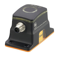
Valve actuators are categorized based upon a number of factors including power source available, torque necessary to operate the valve, installation location, and the need for automatic actuation. Actuators are devices which supply the force and motion to open and close valves. They can be manually, pneumatically, hydraulically, or electrically operated. In common industrial usage, the term actuator generally refers to a device which employs a non-human power source and can respond to a controlling signal.
Types of actuators include:
- Manual handwheel or lever
- Electrical motor
- Pneumatic
- Hydraulic
 |
| Gear Operator |
Manual actuators are capable of placing the valve in any position but do not permit automatic operation. The most common type mechanical actuator is the handwheel. This type includes handwheels fixed to the stem, hammer handwheels, and handwheels connected to the stem through gears.
If additional mechanical advantage is necessary for a manually-operated valve, the valve bonnet is fitted with manually-operated gear heads as illustrated in Figure 32. A special wrench or handwheel attached to the pinion shaft permits one individual to operate the valve when two individuals might be needed without the gear advantage. Because several turns of the pinion are necessary to produce one turn of the valve stem, the operating time of large valves is exceptionally long. The use of portable air motors connected to the pinion shaft decreases the valve operating time.
 |
| Electric Actuator |
Electric motors permit manual, semi-automatic, and automatic operation of the valve. Motors are used mostly for open-close functions, although they are adaptable to positioning the valve to any point opening as illustrated in Figure 33. The motor is usually a, reversible, high speed type connected through a gear train to reduce the motor speed and thereby increase the torque at the stem. Direction of motor rotation determines direction of disk motion. The electrical actuation can be semi-automatic, as when the motor is started by a control system. A handwheel, which can be engaged to the gear train, provides for manual operating of the valve. Limit switches are normally provided to stop the motor automatically at full open and full closed valve positions. Limit switches are operated either physically by position of the valve or torsionally by torque of the motor.
 |
| Pneumatic Actuator |
Pneumatic actuators as illustrated in Figure 34 provide for automatic or semi- automatic valve operation. These actuators translate an air signal into valve stem motion by air pressure acting on a diaphragm or piston connected to the stem. Pneumatic actuators are used in throttle valves for open-close positioning where fast action is required. When air pressure closes the valve and spring action opens the valve, the actuator is termed direct- acting. When air pressure opens the valve and spring action closes the valve, the actuator is termed reverse- acting. Duplex actuators have air supplied to both sides of the diaphragm. The differential pressure across the diaphragm positions the valve stem. Automatic operation is provided when the air signals are automatically controlled by circuitry. Semi-automatic operation is provided by manual switches in the circuitry to the air control valves.
 |
| Hydraulic Actuator |
Hydraulic actuators provide for semi-automatic or automatic positioning of the valve, similar to the pneumatic actuators. These actuators use a piston to convert a signal pressure into valve stem motion. Hydraulic fluid is fed to either side of the piston while the other side is drained or bled. Water or oil is used as the hydraulic fluid. Solenoid valves are typically used for automatic control of the hydraulic fluid to direct either opening or closing of the valve. Manual valves can also be used for controlling the hydraulic fluid; thus providing semi-automatic operation.
For more information on valve actuators and valve automation, contact Thompson Equipment Company (TECO) by calling 800-528-8997 of
visit the valve automation area of their web site here.


