Showing posts with label Valve Automation. Show all posts

What Are Valve Actuators?

Valve actuators are categorized based upon a number of factors including power source available,  torque necessary to operate the valve, installation location,  and the need for automatic actuation.  Actuators are devices which supply the force and motion to open and close valves. They can be manually, pneumatically, hydraulically, or electrically operated. In common industrial usage, the term actuator generally refers to a device which employs a non-human power source and can respond to a controlling signal.

Types of actuators include:


  • Manual handwheel or lever
  • Electrical motor
  • Pneumatic
  • Hydraulic

Gear Operator
Gear Operator

Manual Actuators

Manual actuators are capable of placing the valve in any position but do not permit automatic operation. The most common type mechanical actuator is the handwheel. This type includes handwheels fixed to the stem, hammer handwheels, and handwheels connected to the stem through gears.

Gear Operators

If additional mechanical advantage is necessary for a manually-operated valve, the valve bonnet is fitted with manually-operated gear heads as illustrated in Figure 32. A special wrench or handwheel attached to the pinion shaft permits one individual to operate the valve when two individuals might be needed without the gear advantage. Because several turns of the pinion are necessary to produce one turn of the valve stem, the operating time of large valves is exceptionally long. The use of portable air motors connected to the pinion shaft decreases the valve operating time.

Electric Actuators

Electric Actuator
Electric Actuator
Electric motors permit manual, semi-automatic, and automatic operation of the valve. Motors are used mostly for open-close functions, although they are adaptable to positioning the valve to any point opening as illustrated in Figure 33. The motor is usually a, reversible, high speed type connected through a gear train to reduce the motor speed and thereby increase the torque at the stem. Direction of motor rotation determines direction of disk motion. The electrical actuation can be semi-automatic, as when the motor is started by a control system. A handwheel, which can be engaged to the gear train, provides for manual operating of the valve. Limit switches are normally provided to stop the motor automatically at full open and full closed valve positions. Limit switches are operated either physically by position of the valve or torsionally by torque of the motor.


Pneumatic Actuators

Pneumatic Actuator
Pneumatic Actuator
Pneumatic actuators as illustrated in Figure 34 provide for automatic or semi- automatic valve operation. These actuators translate an air signal into valve stem motion by air pressure acting on a diaphragm or piston connected to the stem. Pneumatic actuators are used in throttle valves for open-close positioning where fast action is required. When air pressure closes the valve and spring action opens the valve, the actuator is termed direct- acting. When air pressure opens the valve and spring action closes the valve, the actuator is termed reverse- acting. Duplex actuators have air supplied to both sides of the diaphragm. The differential pressure across the diaphragm positions the valve stem. Automatic operation is provided when the air signals are automatically controlled by circuitry. Semi-automatic operation is provided by manual switches in the circuitry to the air control valves.

Hydraulic Actuators


Hydraulic Actuator
Hydraulic Actuator
Hydraulic actuators provide for semi-automatic or automatic positioning of the valve, similar to the pneumatic actuators. These actuators use a piston to convert a signal pressure into valve stem motion. Hydraulic fluid is fed to either side of the piston while the other side is drained or bled. Water or oil is used as the hydraulic fluid. Solenoid valves are typically used for automatic control of the hydraulic fluid to direct either opening or closing of the valve. Manual valves can also be used for controlling the hydraulic fluid; thus providing semi-automatic operation.

For more information on valve actuators and valve automation, contact Thompson Equipment Company (TECO) by calling 800-528-8997  of visit the valve automation area of their web site here.

Thank You To Our Customers - A TECO Crawfish Boil

TECO occasionally hosts crawfish boils at our customers' facilities. We think this is a great way to say thanks and to do something a little out of the ordinary for them. It gives everyone an opportunity to get to know each other, tell a good story and maybe have a laugh or two - all around some really great food.


Thompson Equipment Company
Flow Meter Remanufacturing, Custom Flow Solutions, Full Service Repair, Calibration, and Valve Automation Center. http://www.teco-inc.com | 800-528-8997

New Smart Valve Sensor Provides Preventive Maintenance Diagnostics on Quarter-Turn Valves

MVQ 101
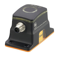
The ifm MVQ101 Smart
Valve Monitor
Good news for valve automation companiesifm’s new smart valve sensor, the MVQ101, provides continuous position feedback and preventive maintenance diagnostics on quarter-turn valves. The sensor features built-in functions that can identify different wear conditions via IO-Link, ifm’s digital communication interface. For example, the sensor can indicate a change in the valve’s operation, which can be a warning that deposits are interfering with the valve’s ability to close or that the seal is wearing.

https://teco-inc.com
800-528-8997


Industrial Plug Valves

plug valve
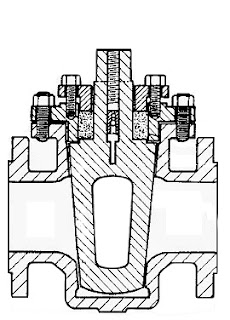
Plug valve diagram showing
plug shape and orifice.
There are common components to be found on almost every process system that involves fluid control. Regardless of the operation's scale, pumps, piping, tanks and valves are likely to be part of the system.

Valves, of which there are many types, provide control over the flow rate, direction and routing of fluids in a processing operation. Flow can be started, stopped or modulated between zero and full rate using a properly sized and configured valve. Some valves enable media flow to be diverted to a selection of outlets, in lieu of a single inlet and outlet pair. Specialized valves regulate inlet or outlet pressure, or prevent fluid flow from going in an undesirable direction. All of these capabilities are packaged into differing valve product offerings that present a very large selection array to a process designer or engineer.

Industrial flow control valve types are generally classified according to the structure or arrangement contained within the valve body that provides obstruction to fluid flow. Some of the common types are ball, butterfly, gate, globe, and plug. Surely, there are more valve types, and this article is not intended to list them all. Some of our previous blogs have discussed selection considerations for gate, ball and butterfly valves. This article will focus on one of the oldest valve types, the plug valve.

Plug valves, like ball and butterfly valves, span from fully open to fully closed positions with a shaft rotation of 90 degrees. The “plug” in a plug valve is installed in the flow path within the valve body and rotated by means of a stem or shaft extending to the exterior of the body. Plugs are often tapered toward the bottom and are fitted to a seating surface in the valve body cavity that prevents fluid from bypassing the plug. An opening through the plug, the port, can be shaped to provide particular flow characteristics. There are numerous variants of the basic plug valve which may make it suitable for particular applications. One common variant is the lined or sleeved plug valve, with an insert or interior lining of material that creates an isolating barrier between the valve body and the media. This allows use of less expensive materials for the body construction that may be otherwise subject to corrosion by exposure to aggressive media.

Plug valve advantages:
  • 90 degree rotation from open to closed provides fast operation.
  • With proper configuration, can be well suited for frequent operation.
  • Availability of corrosion resistant liner may provide comparative cost savings because valve body can be constructed of less expensive material.
  • Design is simple and employs a low parts count.
  • Valve can be serviced in place.
  • Generally, low resistance to flow when fully open.
  • Reliable leak-tight service due to tapered plug wedging action, replaceable sleeve, and injection of lubricant in some variants.
Plug valve disadvantages:
  • Higher friction in the plug closure mechanism may require comparatively higher operating torque than other valve types.
  • Without a specially designed plug, generally not well suited for throttling applications.
  • Rapid shutoff delivered by plug design may not be suitable for some applications where hammering may occur.
Share your fluid control application challenges with a valve and automation specialist. Leverage your own knowledge and experience with their product application expertise to develop an effective solution.

Contact Thompson Equipment (TECO) for all your valve automation and valve repair needs.

https://teco-inc.com
800-528-8997

Industrial Control Valve Design and Operation

Control valves
The design and operation of industrial control valves  is very important to understand if you work as a process engineer, a plant maintenance person, or if you design process control loops.

Control valves are used extensively in power plants, pulp and paper mills, chemical manufacturing, petro-chemical processing, HVAC and steam distribution systems.

There are many types, manufacturers, body styles, and specialized features, but the they all share some basics operating principles. The video below explains components, operation, and fundamentals.

TECO designs automated control valve systems for all major industries including chemical, pulp and paper, petro-chemical, power generation, and water treatment.  TECO’s experience and engineering background make them a uniquely qualified partner for your next automated valve requirement.

https://www.teco-inc.com
800-528-8997

Industrial Valve Actuators and Valve Automation

Pneumatic Valve Actuator
Pneumatic Valve Actuator (white)
Actuators are devices which supply the force and motion to open and close valves. They can be manually, pneumatically, hydraulically, or electrically operated. In common industrial usage, the term actuator generally refers to a device which employs a non-human power source and can respond to a controlling signal. Handles and wheels, technically manual actuators, are not usually referred to as actuators. They do not provide the automation component characteristic of powered units.

The primary function of a valve actuator is to set and hold the valve position in response to a process control signal. Actuator operation is related to the valve on which it is installed, not the process regulated by the valve. Thus a general purpose actuator may be used across a broad range of applications.

Electric Valve Actuator
Electric Valve Actuator (blue)
In a control loop, the controller has an input signal parameter, registered from the process, and compares it to a desired setpoint parameter. The controller adjusts its output to eliminate the difference between the process setpoint and process measured condition. The output signal then drives some control element, in this case the actuator, so that the error between setpoint and actual conditions is reduced. The output signal from the controller serves as the input signal to the actuator, resulting in a repositioning of the valve trim to increase or decrease the fluid flow through the valve.

An actuator must provide sufficient force to open and close its companion valve. The size or power of
the actuator must match the operating and torque requirements of the companion valve. After an evaluation is done for the specific application, it may be found that other things must be accommodated by the actuator, such as dynamic fluid properties of the process or the seating and unseating properties of the valve. It is important that each specific application be evaluated to develop a carefully matched valve and actuator for the process.

Hydraulic and electric actuators are readily available in multi-turn and quarter-turn configurations. Pneumatic actuators are generally one of two types applied to quarter-turn valves: scotch-yoke and rack and pinion. A third type of pneumatic actuator, the vane actuator, is also available.

For converting input power into torque, electric actuators use motors and gear boxes while pneumatic actuators use air cylinders. Depending on torque and force required by the valve, the motor horsepower, gearing, and size of pneumatic cylinder may change.

There are almost countless valve actuator variants available in the industrial marketplace. Many are tailored for very narrow application ranges, while others are more generally applied. Special designs can offer more complex operating characteristics. Ultimately, when applying actuators to any type of device, consultation with an application specialist is recommended to help establish and attain proper performance, safety and cost goals, as well as evaluation and matching of the proper actuator to the valve operation requirements. Share your fluid process control requirements with a specialist in valve automation, combining your own process knowledge and experience with their product application expertise to develop effective solutions.

Rack and Pinion Pneumatic Valve Actuators

Rack and pinion actuator
(courtesy of Jamesbury)
There are three primary categories of valve actuators commonly used valve automation:
  • Pneumatic
  • Hydraulic
  • Electric
Pneumatic actuators can be further categorized as:
  • Scotch yoke design
  • Vane design
  • Rack and pinion actuators (the subject of this post).
Animation of how rack
and pinion gears convert linear
motion to rotational motion.
Rack and pinion actuators provide a rotational movement designed to open and close quarter-turn valves such as ball, butterfly, or plug valves and also for operating industrial or commercial dampers.

The rotational movement of a rack and pinion actuator is accomplished via linear motion and two gears. A circular gear, referred to a “pinion” engages the teeth of a linear gear “bar” referred to as the “rack”.

Pneumatic actuators use pistons that are attached to the rack. As air or spring power is applied the to pistons, the rack is “pushed” inward or “pulled” outward. This linear movement is transferred to the rotary pinion gear (in both directions) providing bi-directional rotation.


Rack and pinion gear configuration
Actuator rack & pinion gear configuration
Rack and pinion actuators pistons can be pressurized with air, gas, or oil to provide the linear the movement that spins the pinion gear. To rotate the pinion gear in the opposite direction, the air, gas, or oil must be redirected to the other sides of the piston, or use coil springs as the energy source for rotation. Rack and pinion actuators using springs are referred to as "spring-return actuators". Actuators that rely on opposite side pressurization of the rack are referred to as "direct acting".
Most actuators are designed for 100-degree travel with clockwise and counterclockwise travel adjustment for open and closed positions. World standard ISO mounting pad are commonly available to provide ease and flexibility in direct valve installation.

NAMUR mounting dimensions on actuator pneumatic port connections and on actuator accessory holes and drive shaft are also common design features to make adding pilot valves and accessories more convenient.

Pneumatic pneumatic rack and pinion actuators are compact and save space. They are reliable, durable and provide a good life cycle. There are many brands of rack and pinion actuators on the market, all with subtle differences in piston seals, shaft seals, spring design and body designs.

For more information on any pneumatic or electric valve automation project, visit this link or call TECO at 800-528-8997.

An Introduction to Industrial Valve Actuators

Industrial Valve Actuators
Industrial Valves and Valve Actuators
Valves are essential to industries which constitute the backbone of the modern world. The prevalence of valves in engineering, mechanics, and science demands that each individual valve performs to a certain standard. Just as the valve itself is a key component of a larger system, the valve actuator is as important to the valve as the valve is to the industry in which it functions. Actuators are powered mechanisms that position valves between open and closed states; the actuators are controllable either by manual control or as part of an automated control loop, where the actuator responds to a remote control signal. Depending on the valve and actuator combination, valves of different types can be closed, fully open, or somewhere in-between. Current actuation technology allows for remote indication of valve position, as well as other diagnostic and operational information. Regardless of its source of power, be it electric, hydraulic, pneumatic, or another, all actuators produce either linear or rotary motion under the command of a control source.

Thanks to actuators, multiple valves can be controlled in a process system in a coordinated fashion; imagine if, in a large industrial environment, engineers had to physically adjust every valve via a hand wheel or lever! While that manual arrangement may create jobs, it is, unfortunately, completely impractical from a logistical and economic perspective. Actuators enable automation to be applied to valve operation.

Pneumatic actuators utilize air pressure as the motive force which changes the position of a valve. Pressurized-liquid reliant devices are known as hydraulic actuators. Electric actuators, either motor driven or solenoid operated, rely on electric power to drive the valve trim into position. With controllers constantly monitoring a process, evaluating inputs, changes in valve position can be remotely controlled to provide the needed response to maintain the desired process condition.

Manual operation and regulation of valves is becoming less prevalent as automation continues to gain traction throughout every industry. Valve actuators serve as the interface between the control intelligence and the physical movement of the valve. The timeliness and automation advantages of the valve actuators also serve as an immense help in risk mitigation, where, as long as the system is functioning correctly, critical calamities in either environmental conditions or to a facility can be pre-empted and quickly prevented. Generally speaking, manual actuators rely on hand operation of levers, gears, or wheels, but valves which are frequently changed (or which exist in remote areas) benefit from an automatic actuator with an external power source for a myriad of practical reasons, most pressingly being located in an area mostly impractical for manual operation or complicated by hazardous conditions.

Thanks to their versatility and stratified uses, actuators serve as industrial keystones to, arguably, one of the most important control elements of industries around the world. Just as industries are the backbones of societies, valves are key building blocks to industrial processes, with actuators as an invaluable device ensuring both safe and precise operation.

Thompson Equipment (TECO) specifies, designs, and fabricates complete valve automation solutions for a wide variety of industries. Contact TECO for your next valve automation requirement.

Valve Automation Professionals Will Save You Time and Money on Your Next Industrial Valve Project

Teco Valve Automation Expert
Local Distributors and Reps provide great value when
working on automated valve projects.
Local distributors and representatives who sell industrial valves, actuators and controls also provide services and equipment that will save you time, money, and help you achieve a better outcome for the entire project.

Projects requiring engineered valve systems are best completed and accomplished through the proper selection and application of the valves, actuators, positioners, limit switches and other associated components. A great resource exists, ready to provide a high level of technical knowledge and assistance, that can be easily tapped to help you with your project - the valve automation sales professional.

Consider a few of the things the valve automation professional brings to your project:

Product Knowledge: Valve automation professionals are current on product offerings, proper application technique, and product capabilities. They also posses  information on future product obsolescence and upcoming new designs. This type of information is not generally accessible to the public via the Internet.

Experience: As a project engineer, you may be treading on new ground regarding some aspects of your current valve system design assignment. There can be real benefit in connecting to an experienced and highly knowledgable source, with past exposure to your current challenges.

Access: Through a valve automation professional, you may be able to establish a connection to “behind the scenes” manufacturer contacts with essential information not publicly available. The rep knows people at the factories, a well as at other valve related companies, who can provide quick and accurate answers to your valve automation related questions.

Of course, any valve actuation or automation solution proposed are likely to be based upon the products sold by the representative. That is where considering and evaluating the benefits of any solution becomes part of achieving the best project outcome.

Develop a professional, mutually beneficial relationship with a local valve automation professional to make your design job go after, more efficiently, and more cost effective. Their success is tied to your success, and they are eager to help you.