The mathematical relationship between fluid velocity and turbine tip velocity – assuming frictionless conditions – is a ratio defined by the tangent of the turbine blade angle:
For a 45o blade angle, the relationship is 1:1, with tip velocity equaling fluid velocity. Smaller blade angles (each blade closer to parallel with the fluid velocity vector) result in the tip velocity being a fractional proportion of fluid velocity.
Turbine tip velocity is quite easy to sense using a magnetic sensor, generating a voltage pulse each time one of the ferromagnetic turbine blades passes by. Traditionally, this sensor is nothing more than a coil of wire in proximity to a stationary magnet, called a pickup coil or pickoff coil because it “picks” (senses) the passing of the turbine blades. Magnetic flux through the coil’s center increases and decreases as the passing of the steel turbine blades presents a varying reluctance (“resistance” to magnetic flux), causing voltage pulses equal in frequency to the number of blades passing by each second. It is the frequency of this signal that represents fluid velocity, and therefore volumetric flow rate.
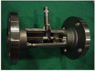
A cut-away demonstration model of a turbine flowmeter is shown in the following photograph. The blade sensor may be seen protruding from the top of the flowtube, just above the turbine wheel:
 |
| Turbine flowmeter cutaway |
Mechanical gears and rotating cables have also been historically used to link a turbine flowmeter’s turbine wheel to indicators. These designs suffer from greater friction than electronic (“pickup coil”) designs, potentially resulting in more measurement error (less flow indicated than there actually is, because the turbine wheel is slowed by friction). One advantage of mechanical turbine flowmeters, though, is the ability to maintain a running total of gas usage by turning a simple odometer-style totalizer. This design is often used when the purpose of the flowmeter is to track total fuel gas consumption (e.g. natural gas used by a commercial or industrial facility) for billing.
For more information on turbine flowmeters, contact Thompson Equipment Company (TECO) by visiting their website at http://www.teco-inc.com or call 800-528-8997.
Reprinted from "Lessons In Industrial Instrumentation" by Tony R. Kuphaldt under the Creative Commons Attribution 4.0 International Public License.

