An Introduction to Industrial Valve Actuators

Industrial Valve Actuators
Industrial Valves and Valve Actuators
Valves are essential to industries which constitute the backbone of the modern world. The prevalence of valves in engineering, mechanics, and science demands that each individual valve performs to a certain standard. Just as the valve itself is a key component of a larger system, the valve actuator is as important to the valve as the valve is to the industry in which it functions. Actuators are powered mechanisms that position valves between open and closed states; the actuators are controllable either by manual control or as part of an automated control loop, where the actuator responds to a remote control signal. Depending on the valve and actuator combination, valves of different types can be closed, fully open, or somewhere in-between. Current actuation technology allows for remote indication of valve position, as well as other diagnostic and operational information. Regardless of its source of power, be it electric, hydraulic, pneumatic, or another, all actuators produce either linear or rotary motion under the command of a control source.

Thanks to actuators, multiple valves can be controlled in a process system in a coordinated fashion; imagine if, in a large industrial environment, engineers had to physically adjust every valve via a hand wheel or lever! While that manual arrangement may create jobs, it is, unfortunately, completely impractical from a logistical and economic perspective. Actuators enable automation to be applied to valve operation.

Pneumatic actuators utilize air pressure as the motive force which changes the position of a valve. Pressurized-liquid reliant devices are known as hydraulic actuators. Electric actuators, either motor driven or solenoid operated, rely on electric power to drive the valve trim into position. With controllers constantly monitoring a process, evaluating inputs, changes in valve position can be remotely controlled to provide the needed response to maintain the desired process condition.

Manual operation and regulation of valves is becoming less prevalent as automation continues to gain traction throughout every industry. Valve actuators serve as the interface between the control intelligence and the physical movement of the valve. The timeliness and automation advantages of the valve actuators also serve as an immense help in risk mitigation, where, as long as the system is functioning correctly, critical calamities in either environmental conditions or to a facility can be pre-empted and quickly prevented. Generally speaking, manual actuators rely on hand operation of levers, gears, or wheels, but valves which are frequently changed (or which exist in remote areas) benefit from an automatic actuator with an external power source for a myriad of practical reasons, most pressingly being located in an area mostly impractical for manual operation or complicated by hazardous conditions.

Thanks to their versatility and stratified uses, actuators serve as industrial keystones to, arguably, one of the most important control elements of industries around the world. Just as industries are the backbones of societies, valves are key building blocks to industrial processes, with actuators as an invaluable device ensuring both safe and precise operation.

Thompson Equipment (TECO) specifies, designs, and fabricates complete valve automation solutions for a wide variety of industries. Contact TECO for your next valve automation requirement.
Basics and Practice of Applying ABB Rotameters (Variable Area Flowmeters)

ABB Variable Area flowmeters
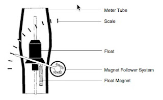
Diagram of rotameter
(courtesy of ABB)
For decades variable Area flowmeters have become established in industrial measure- ment technology with an economical, mature measurement principle. The large variety of instrument designs, their repeatability and independence from supply power require- ments for local indication provide a suitable solution in almost every flow metering ap- plication for liquids, gases and steam.

The ABB-Program includes, a line of metal meter tube flowmeters particularly suited for high pressure and temperature applications, for aggressive and opaque fluids and for steam metering. Also offered is a line of glass meter tube flowmeters (the solution for extremely low pressure conditions) including float designs for viscous fluids or high flowrates in the smaller sizes. The purge flowmeters in both lines are available with a differential pressure regulator to maintain a constant flowrate even when there are pressure variations. The smallest flow ranges required in laboratory applications and high flowrates in industrial applications can be satisfied with ABB instruments.

This new “Handbook for Variable Area Flowmeters“ is a practical guide for the user with selection criteria for real applications (see Check List/Parameter Questionnaire), correction factors, Accuracy Classes, corrosion resistance tables and much more. A separate flyer with actual pictures demonstrate the application versatility.

Answers are provided to frequently asked questions about this measurement principle (see Page 20) and we have incorporated a preferential quick ship program for the most popular instrument versions.

We hope that this Handbook provides you with a practical selection guide; naturally our sales team is always ready to provide you with any personal assistance you may require.

For more information on any ABB variable area flow meter (rotameter), visit TECO at http://www.teco-inc.com or call (504) 833-6381.

Bubble Tube Purge for Level Measurement

ABB Rotameter
ABB Rotameter
Description of Application

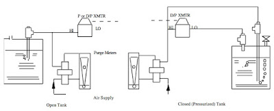
One of the most widely used methods of monitoring/controlling liquid level in a tank is the use of Bubble Tubes with Pressure or Differential Pressure Transmitters. A small, but uninterrupted flow of air or inert gas is forced down through a dip tube which extends to near the bottom of the tank. The back pressure of the introduced gas is a function of the liquid level or head in the tank.

Where Used
  • Chemical Companies
  • Food & Beverage Companies
How Installed

Bubble Tube Purge for Level Measurement
Bubble Tube Purge for Level Measurement (click for larger view)


Rotameter Solution

The use of a Purge type Rotameter is the least expensive and most convenient way to set and monitor the flow of air or inert gas into the Bubble Tube.

Method Of Operation


A small, but uninterrupted flow of air (or inert gas such as nitrogen) is easily set and monitored by the use of a Purge Type Rotameter. The flow rate must be low to insure no increase in head back pressure due to pressure drop through the purge piping and dip tube. Conversely the flow cannot be interrupted or the back pressure may decrease below that of the head giving an incorrect level reading and possibly allowing the process liquid to reflux back to the purgemeter and ∆/P Transmitter. Note that controlling the exact flow rate is not critical. The flow rate must be low and uninterrupted. The purge supply gas pressure must exceed the maximum line pressure by about 10psi.

For more information, contact Thompson Equipment at 800-528-8997 or visit http://www.teco-inc.com.

Valve Automation Professionals Will Save You Time and Money on Your Next Industrial Valve Project

Teco Valve Automation Expert
Local Distributors and Reps provide great value when
working on automated valve projects.
Local distributors and representatives who sell industrial valves, actuators and controls also provide services and equipment that will save you time, money, and help you achieve a better outcome for the entire project.

Projects requiring engineered valve systems are best completed and accomplished through the proper selection and application of the valves, actuators, positioners, limit switches and other associated components. A great resource exists, ready to provide a high level of technical knowledge and assistance, that can be easily tapped to help you with your project - the valve automation sales professional.

Consider a few of the things the valve automation professional brings to your project:

Product Knowledge: Valve automation professionals are current on product offerings, proper application technique, and product capabilities. They also posses  information on future product obsolescence and upcoming new designs. This type of information is not generally accessible to the public via the Internet.

Experience: As a project engineer, you may be treading on new ground regarding some aspects of your current valve system design assignment. There can be real benefit in connecting to an experienced and highly knowledgable source, with past exposure to your current challenges.

Access: Through a valve automation professional, you may be able to establish a connection to “behind the scenes” manufacturer contacts with essential information not publicly available. The rep knows people at the factories, a well as at other valve related companies, who can provide quick and accurate answers to your valve automation related questions.

Of course, any valve actuation or automation solution proposed are likely to be based upon the products sold by the representative. That is where considering and evaluating the benefits of any solution becomes part of achieving the best project outcome.

Develop a professional, mutually beneficial relationship with a local valve automation professional to make your design job go after, more efficiently, and more cost effective. Their success is tied to your success, and they are eager to help you.

Basics of Process Piping: Piping & Instrument Diagrams

P&ID's (piping & instrumentation diagrams), or Process and Control Flow Diagrams, are schematic representations of a process control system and used to illustrate the piping system, process flow, installed equipment, and process instrumentation and functional relationships therein.

P&ID’s can be very detailed and are generally the primary source from where instrument and equipment lists are generated and are very handy reference for maintenance and upgrades. P&ID’s also play an important early role in safety planning through a better understanding of the operability and relationships of all components in the system.

Intended to provide a “picture” of all of piping including the physical branches, valves, equipment, instrumentation and interlocks. The P&ID uses a set of standard symbols representing each component of the system such as instruments, piping, motors, pumps, etc.

For more information on any process instrument question or requirement, feel free to contact the application engineers at Thompson Equipment. For immediate service call 800-528-8997

Custom Magmeters for the Most Abrasive and Erosive Slurry Application

custom magmeter
Custom magnetic flowmeter with
engineered ceramic
brick liner.
When you have suspended solids, such as cement, coal, or fly ash, mixed with a liquid (such as water), a mud-like substance referred to as a “slurry” is formed. Measuring flow of slurries is often times challenging because of their abrasive nature and the wear and tear flowmeters experience. Add to the challenge a carrier fluid that is highly caustic or acidic, and the flow measurement task becomes geometrically more difficult.

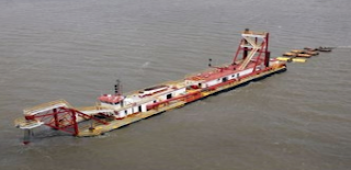
In certain industries this situation is very common. Slurry processing applications in mining, dredging, pulp & paper, fracking, oil and gas exploration (drilling slurries - not the old or gas), and wastewater treatment all have areas that present a variety of highly erosive and corrosive slurries. In these situations off-the-shelf magnetic flowmeters won’t last, so consideration must be given to custom flowmeters built specifically to withstand the application’s unique requirements. A complete understanding of the composition of the chemical and particulate nature of the slurry and the flow conditions is critical.
dredging
Dredging is an example of challenging slurry flow measurement. 

Customized magnetic flowmeters with very high erosion and abrasion resistance incorporate specialized materials and unique features that increase the performance and service life for that application. These flowmeters are highly engineered and the selection of a manufacturer with the experience, production capability, and quality control is imperative.

Here is a partial list of specialized features available from custom flowmeter manufacturers:

Specialty liners:

  • Magnesia stabilized Zirconia ceramic
  • Aluminum Oxide ceramic
  • Polyurethane rubber
  • Neoprene rubber
  • Linatex
  • Teflon (PTFE)
  • Rotationally molded Tefzel (ETFE)
  • PFA

Specialty electrodes: 

  • Stainless Steel
  • Hastalloy B/C
  • Titanium
  • Platinum/Iridium
  • Tungston Carbide

Exotic Tube Construction:

  • 100% Titanium
  • Marine Epoxy paints
  • Powder coating

In summary, when faced with measuring the flow of a highly erosive and abrasive slurry, it’s best to call upon a company with the expertise and production capabilities to match the flowmeter design exactly with the application requirements. Take the time to do this up front, and resist the temptation to “wing-it” with and install a generically designed flowmeter. Doing so will pay off in service life and overall cost in the long run.

The Operating Principles of a Magnetic Flowmeter

Below is a video, courtesy of Badger Meter, illustrating the operating principles of magnetic flowmeters (also known as magmeters).

A magnetic field is applied to the flow tube, resulting in an EMF proportional to the flow velocity passing perpendicular to the magnetic flux lines. The physical principle at work is Faraday's law of electromagnetic induction.

Magnetic flow meter requires a conductive fluid, and electrically insulated internal pipe surfaces to operate.

Advantages:
  • Low maintenance cost
  • No moving parts
  • Good for slurry
  • Good for corrosive fluids
  • Very linear
  • Minimal flow restriction

Disadvantages:
  • Requires electrically conductive fluids
For more information on magmeters, visit TECO at http://www.teco-inc.com of call 800-528-8997.