 |
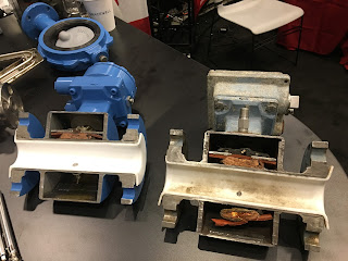
| Magnetic flow meter. |
Magnetic flow meters are effective for monitoring the flow rate of fluids that present difficult handling problems, such as corrosive acids, sewage, rock and acid slurries, sand and water slurries, paper pulp stock, rosin size, detergents, bleaches, dyes, emulsions, tomato pulp, milk, soda, and beer. Magnetic flow meters mainly are applicable to liquids that have a conductivity of 0.1 microsiemens per centimeter or greater. They are not applicable to petroleum products or gases.
Measurement Principal
The basis of the magnetic flow meter is Faraday's Law of Electromagnetic Induction. In summary, a voltage induced in a conductor (i.e., the fluid flowing in the conduit) moving in a magnetic field is proportional to the velocity of the conductor. This relationship can be expressed mathematically as follows:
 |
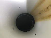
| Internal view of flow tube. |
E=C×B×D×v
where:
E = induced voltage
C = constant
B = magnetic flux density
D = diameter of conduit
v = velocity of fluid
In principle, the fluid flowing through the pipe passes through the magnetic field. This action generates a voltage that is linearly proportional to the average velocity in the plane of the electrodes. If the velocity profile changes due to swirl or helical flow patterns, the total measured velocity is unaffected as long as the velocity profile across the pipe is symmetrical. Non-symmetrical flow profiles may cause flow rate measurement errors of several percent.
In operation, the magnetic coils create a magnetic field that passes through the flow tube and into the process fluid. When the conductive fluid flows through the flow meter, a voltage is induced between the electrodes, which are in contact with the process fluid and isolated electrically from the pipe walls by a nonconductive liner to prevent a short circuit in the electrode signal voltage. Grounding is required for magnetic flow meters to shield the relatively low voltage signal that is measured at the electrodes from the relatively high common-mode potentials that may be present in the fluid. If the pipe is conductive and comes in contact with the flow meter, the flow meter should be grounded to the pipe both upstream and downstream of the flow meter. If the pipe is constructed of a nonconductive material, such as plastic, or a conductive material that is insulated from the process fluid, such as plastic-lined steel pipe, grounding rings should be installed in contact with the liquid.
Magnetic flow meters can be used in pipes that range in diameter from 0.25 to 240 cm (0.1 to 96 in.). Magnetic flow meters are available for flow rates in the range of 0.008 liters per minute (L/min) (0.002 gallons per minute [gal/min]) to 570,000 L/min (150,000 gal/min). Since magnetic flow meters do not place an obstruction in the pipe, the devices do not cause a loss in fluid pressure. Also, straight pipe requirements do not apply to this flow monitor device. Magnetic flow meters are insensitive to density and viscosity and can measure flow in both directions. In addition, because they cause no obstructions, magnetic flow meters often are used to measure the flow rate of slurries.
Accuracy
If all components of a magnetic flow metering system are calibrated as a unit, system accuracies of ±0.5 percent of flow rate are possible. However, normal accuracy specifications are ±1.0 percent of flow rate. Higher accuracy systems match the primary flow meter with a transmitter in the factory.
For more information on magnetic flow meters, contact
TECO by calling 800-528-8997 or visit their web site at
https://teco-inc.com.


