Water Flow Metering and Measurement

water flow measurement devices
Water flow measurement device comparison (click for larger view)
Water is commonly measured and sold in volumetric measurements, which allows for lower-cost metering options. The specific measurement technology chosen will depend on a number of factors including, but not limited to, current design, budget, accuracy requirements, resolution, minimum flow rate, potable versus non-potable (or at least filtered versus non-filtered water), range of flow rates, and maximum flow rate.

Volumetric water measurement can be broken down into three general operating designs:
  • Positive displacement
  • Differential pressure
  • Velocity

Positive Displacement – Nutating-Disk Flow Meter

Nutating-disk flow meters are the most common meter technology used by water utilities to measure potable-water consumption for service connections up to 3-inch. The nutating-disk flow meter consists of a disk mounted on a spherically shaped head and housed in a measuring chamber. As the fluid flows through the meter passing on either side of the disk, it imparts a rocking or nutating motion to the disk. This motion is then transferred to a shaft mounted perpendicular to the disk. It is this shaft that traces out a circular motion – transferring this action to a register that records flow.

There are a variety of differential pressure devices useful for water metering; two of the more common devices include orifice flow meters and venturi flow meters.

Differential Pressure – Orifice Flow Meter

The orifice element is typically a thin, circular metal disk held between two flanges in the fluid stream. The center of the disk is formed with a specific-size and shape hole, depending on the expected fluid flow parameters (e.g., pressure and flow range). As the fluid flows through the orifice, the restriction creates a pressure differential upstream and downstream of the orifice proportional to the fluid flow rate. This differential pressure is measured and a flow rate calculated based on the differential pressure and fluid properties.

Differential Pressure – Venturi Flow Meter

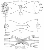
The venturi flow meter takes advantage of the velocity-pressure relationship when a section of pipe gently converges to a small-diameter area (called a throat) before diverging back to the full pipe diameter. The benefit of the venturi flow meter over the orifice flow meter lies in the reduced pressure loss experienced by the fluid.

The velocity measurement technologies described in this section include the turbine flow meter, vortex-shedding flow meter, and ultrasonic flow meters.

Velocity – Turbine Flow Meter

A multi-blade impellor-like device is located in, and horizontal to, the fluid stream in a turbine flow meter. As the fluid passes through the turbine blades, the impellor rotates at a speed related to the fluid’s velocity. Blade speed can be sensed by a number of techniques including magnetic pick-up, mechanical gears, and photocell. The pulses generated as a result of blade rotation are directly proportional to fluid velocity, and hence flow rate.

Velocity – Vortex-Shedding Flow Meter

A vortex-shedding flow meter senses flow disturbances around a stationary body (called a bluff body) positioned in the middle of the fluid stream. As fluid flows around the bluff body, eddies or vortices are created downstream; the frequencies of these vortices are directly proportional to the fluid velocity.

Velocity – Ultrasonic Flow Meters

There are two different types of ultrasonic flow meters, transit-time and Doppler-effect. The two technologies use ultrasonic signals very differently to determine fluid flow and are best applied to different fluid applications. Transit-time ultrasonic flow meters require the use of two signal transducers. Each transducer includes both a transmitter and a receiver function. As fluid moves through the system, the first transducer sends a signal and the second receives it. The process is then reversed. Upstream and downstream time measurements are compared. With flow, sound will travel faster in the direction of flow and slower against the flow. Transit-time flow meters are designed for use with clean fluids, such as water.

Doppler-effect ultrasonic flow meters use a single transducer. The transducer has both a transmitter and receiver. The high-frequency signal is sent into the fluid. Doppler-effect flow meters use the principal that sound waves will be returned to a transmitter at an altered frequency if reflectors in the liquid are in motion. This frequency shift is in direct proportion to the velocity of the liquid. The echoed sound is precisely measured by the instrument to calculate the fluid flow rate.

Because the ultrasonic signal must pass through the fluid to a receiving transducer, the fluid must not contain a significant concentration of bubbles or solids. Otherwise the high frequency sound will be attenuated and too weak to traverse the distance to the receiver. Doppler-effect ultrasonic flow meters require that the liquid contain impurities, such as gas bubbles or solids, for the Doppler-effect measurement to work. One of the most attractive aspects of ultrasonic flow meters is they are non-intrusive to the fluid flow. An ultrasonic flow meter can be externally mounted to the pipe and can be used for both temporary and permanent metering.

For more information on any flow application, visit http://www.teco-inc.com or call (504) 833-6381.


Natural Gas Flow Metering and Measurement


Natural gas is a hydrocarbon gas mixture consisting primarily methane, but includes a host of other chemical components. Accurate natural gas flow measurement usually requires the measurement of the fluid’s temperature and pressure in addition to flow. Additional constraints on natural gas measurement may include the physical space available or possibly configuration and weight of the metering system. Some of the fluid metering technologies require specific lengths of pipe, both upstream and downstream of the meter for proper function.

Before any technology decisions are made, discussions with equipment vendors and/or design engineers are recommended to ensure proper technology selection and installation design.

Depending on the application, flow rate, installation access, and desired accuracy, there are a number of technology options for natural gas metering. In general, measurement of natural gas volumetric flow rate is represented in standard cubic feet per hour (scfh) or per minute (scfm). The actual mass of gas flowing past a point of measurement changes with its temperature and pressure. Density changes resulting from temperature and pressure differences can result in differences between the energy content of similar volumes of the gas. To equalize the effect of density variations when metering gas, conditions are referenced against standard temperature and pressure conditions, hence standard cubic feet (scf) instead of actual cubic feet (acf). Gas flowmeters must compensate for density differences between standard conditions and actual conditions to accurately define standard flow rates.

The most common volumetric gas metering devices fall into one of the following categories:
  • Positive displacement
  • Differential pressure
  • Velocity 
In most applications, gas flowmeters are installed downstream of pressure regulation devices and the meters are then calibrated to that pressure. Natural gas meters may include options for temperature and pressure compensation.


POSITIVE DISPLACEMENT


A positive displacement meter functions by the fluid physically displacing the measuring mechanism and this displacement becomes the metered value. Of relevancy to natural gas measurement, the two predominant technologies are the diaphragm meter (most common) and the rotary meter. In each case, the volume of gas for measurement physically impinges on a measuring element (flexible diaphragm or rotary blower) to increment a recording dial or other output. The primary advantage of positive displacement flow meters is there are no straight-run piping requirements to establish a flow pattern that can be accurately metered. The primary disadvantage of positive displacement meters is higher pressure drops experienced across the meter at peak flow rates.


DIFFERENTIAL PRESSURE


There are multiple types of differential pressure meters: orifice flow meter, venture flow meter, and annubar flow meter. All differential pressure meters rely on the velocity-pressure relationship of flowing fluids for operation.

Orifice Flow Meter 
The orifice element is typically a thin, circular metal disk held between two flanges in the fluid stream. The center of the disk is formed with a specific-size and shape hole, depending on the expected fluid flow parameters (e.g., pressure and flow range). As the fluid flows through the orifice, the restriction creates a pressure differential upstream and downstream of the orifice proportional to the fluid flow rate. This differential pressure is measured and a flow rate calculated based on the differential pressure and fluid properties.

Venturi Flow Meter
The venturi flow meter takes advantage of the velocity- pressure relationship when a section of pipe gently converges to a small-diameter area (called a throat) before diverging back to the full pipe diameter. The benefit of the venturi flow meter over the orifice flow meter lies in the reduced pressure loss experienced by the fluid.

Annubar Flow Meter
The annubar flow meter (a variation of the simple pitot tube) also takes advantage of the velocity-pressure relationship of flowing fluids. The device causing the change in pressure is a pipe inserted into the natural gas flow.


VELOCITY


There are multiple types of velocity meters: turbine flow meter, vortex-shedding flow meter, and fluid oscillation flow meter. Velocity meters determine fluid flow by measuring a representation of the flow directly. Because the fluid’s velocity is measured (i.e., not the square-root relationship to determine velocity as with differential pressure meters), velocity meters can have better accuracy and usually have better turndown ratios than other meter types.

Turbine Flow Meter
A multi-blade impellor-like device is located in, and horizontal to, the fluid stream in a turbine flow meter. As the fluid passes through the turbine blades, the impellor rotates at a speed related to the fluid’s velocity. Blade speed can be sensed by a number of techniques including magnetic pick-up, mechanical gears, and photocell. The pulses generated as a result of blade rotation are directly proportional to fluid velocity, and hence flow rate.

Vortex-Shedding Flow Meter
A vortex-shedding flow meter senses flow disturbances around a stationary body (called a bluff body) positioned in the middle of the fluid stream. As fluid flows around the bluff body, eddies or vortices are created downstream; the frequencies of these vortices are directly proportional to the fluid velocity.

Fluid Oscillation Flow Meter
A fluid oscillation flow meter uses sensor technology to detect gas oscillations, which corresponds to the flow rate through the meters internal throat design.

For more information on any flow measurement requirement, visit Thompson Equipment (TECO) at http://www.teco-inc.com or call 800-528-8997 for immediate service,

Flow Media Identification in Process Piping

Fluid process control operations use pipes to transport materials over distances. Other processing facilities may also employ piping as a conduit to move a variety of other materials. Factory piping networks move liquids and gasses from process point to process point. An accurate indication of the nature and type of substance or material within a pipe, direction of flow, or other pertinent information, contributes to maintaining a safe and effective operation. Pipe marking and color coding should follow recognized applicable standards that are well known to plant operators. 

With pipe marking following a standardized system, employees and contractors on site, and with knowledge of the applicable marking system, are able to easily understand the different colors and their relation to the facility functions. However, some pipes, such as ammonia refrigeration pipes, have their own, independent standards which can be integrated alongside other identifications. Similarly, pipes used in marine environments bear their own standards, along with specific color combinations and banding. Those two sets of standards comply with the hallmarks of general pipe labeling, coloring and identification, including color coding, simple identification of the pipes content, and the inclusion of an accompanying symbol indicating the direction of the flow. For example, a green pipe with white lettering generally means the adjoining pipe contains potable water, potentially for cooling, boiler feeding, or sinks. All combustible fluids are paired with brown labels and white lettering. In addition to the number of predetermined combinations, user defined pipe color combinations are possible so that businesses may plot certain pipes which do not immediately fit within the preset. These can present a challenge, though, due to the fact that user defined color options will require additional instruction to employees and contractors because of their uniqueness to specific businesses. 

The labels used to identify pipes have their own specifications for size and lettering dimensions. Size requirements for the labels allow for companies to create custom labels while still adhering to universal conditions. The size of the pipe markings is related to the pipe diameter, and meant to ensure visibility. An easy way for businesses to translate pipe labels for their employees is to develop and display color code charts. An employee not immediately familiar with the realm of pipe labeling can quickly reference an accurate, accessible chart before taking any action. The maximization of facility safety relies on ensuring that the pipe color labels are visible, unobstructed, and well-lit. Labels placed every 25-50', especially on a pipe that changes direction, near an access point, or near an end point, place information at important junctures on the pipeline. Clearly understanding both the substance a pipe is carrying and, additionally, how individual pipes constitute the facility network is a key way to mitigate potential process hazards.

Blog post courtesy of Thompson Equipment.

Rack and Pinion Pneumatic Valve Actuators

Rack and pinion actuator
(courtesy of Jamesbury)
There are three primary categories of valve actuators commonly used valve automation:
  • Pneumatic
  • Hydraulic
  • Electric
Pneumatic actuators can be further categorized as:
  • Scotch yoke design
  • Vane design
  • Rack and pinion actuators (the subject of this post).
Animation of how rack
and pinion gears convert linear
motion to rotational motion.
Rack and pinion actuators provide a rotational movement designed to open and close quarter-turn valves such as ball, butterfly, or plug valves and also for operating industrial or commercial dampers.

The rotational movement of a rack and pinion actuator is accomplished via linear motion and two gears. A circular gear, referred to a “pinion” engages the teeth of a linear gear “bar” referred to as the “rack”.

Pneumatic actuators use pistons that are attached to the rack. As air or spring power is applied the to pistons, the rack is “pushed” inward or “pulled” outward. This linear movement is transferred to the rotary pinion gear (in both directions) providing bi-directional rotation.


Rack and pinion gear configuration
Actuator rack & pinion gear configuration
Rack and pinion actuators pistons can be pressurized with air, gas, or oil to provide the linear the movement that spins the pinion gear. To rotate the pinion gear in the opposite direction, the air, gas, or oil must be redirected to the other sides of the piston, or use coil springs as the energy source for rotation. Rack and pinion actuators using springs are referred to as "spring-return actuators". Actuators that rely on opposite side pressurization of the rack are referred to as "direct acting".
Most actuators are designed for 100-degree travel with clockwise and counterclockwise travel adjustment for open and closed positions. World standard ISO mounting pad are commonly available to provide ease and flexibility in direct valve installation.

NAMUR mounting dimensions on actuator pneumatic port connections and on actuator accessory holes and drive shaft are also common design features to make adding pilot valves and accessories more convenient.

Pneumatic pneumatic rack and pinion actuators are compact and save space. They are reliable, durable and provide a good life cycle. There are many brands of rack and pinion actuators on the market, all with subtle differences in piston seals, shaft seals, spring design and body designs.

For more information on any pneumatic or electric valve automation project, visit this link or call TECO at 800-528-8997.

Measuring Flow Using Differential Pressure

Bernoulli's principle
There are several types of flow instruments that rely on the Bernoulli's principle (an increase in the speed of a fluid occurs simultaneously with a decrease in pressure), that measure the differential pressure across the high pressure side and low pressure side of a constriction.

Many industrial processes adapt this principle and measure the differential pressure across an orifice plate or a Venturi tube to measure and control flow.

An orifice plate is a plate with a hole through it. When placed in the pipe, it constricts the flow and provides a pressure differential across the constriction which can be correlated to the flow rate.

A Venturi tube constricts the flow in the same fashion, but instead a plate with a hole, it uses a pipe or tube with a reduced inner diameter to create the flow differential.

This video provides an excellent basic understanding of how this is accomplished. For more information on any type of industrial flow measuring device, visit the TECO website o call 800-528-8997.

NIST Certification of Flow Instrument Calibration and ISO/IEC 17025 Accreditation

The Thompson Equipment Co., Inc., (TECO) facility is used for performing flow calibration for magnetic flow meters as well as other primary liquid flow measuring devices. It is equipped with both mass and volumetric transfer standards.

The output of a customer owned meter is correlated with the output of a standard volumetric meter over a range of its flow capabilities. Each six months, each volumetric standard meter is calibrated against a mass standard. Each year the mass standards are calibrated against the Louisiana Department of Agriculture Standards Laboratory. 

Also on a periodic basis, standards owned by the LA Dept. of Agriculture are calibrated against the National Institute of Standards and Technology (NIST) Each standard device carries with it the appropriate certificate identifying when its last calibration was performed, and by ID number, which standard device it was calibrated against. 

The NIST Traceable Calibration Certificate from TECO documents this trail of calibration so that the calibration of any flow meter can be confirmed all the way back to the NIST Laboratories as is often required by regulatory agencies, ISO-9000 procedures, etc. This provides the user with a high level of confidence in the readings from his instrument.

ISO/IEC 17025 Accredited


TECO's calibration lab is also ISO/IEC 17025 Accredited, meaning it is in accordance with the recognized International Standard ISO/IEC 17025:2005 General requirements for the competence of testing and calibration laboratories. The TECO laboratory also meets any additional program requirements in the field of calibration. This accreditation demonstrates technical competence for a defined scope and the operation of a laboratory quality management system.

Unlike many calibration houses can only verify calibration within the manufacturer's specifications, TECO can provide a wide range of fully accredited flow calibration services to meet virtually any need.

For more information, contact TECO at 800-528-8997 or visit http://teco-inc.com.

Introduction to Transmitters used in Process Control

Flow transmitter
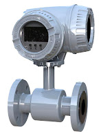
Flow transmitter (ModMag)
Transmitters are process control field devices. They receive input from a connected process sensor, then convert the sensor signal to an output signal using a transmission protocol. The output signal is passed to a monitoring, control, or decision device for use in documenting, regulating, or monitoring a process or operation.

In general, transmitters accomplish three steps, including converting the initial signal twice. The first step is the initial conversion which alters the input signal to make it linear. After an amplification of the converted signal, the second conversion changes the signal into either a standard electrical or pneumatic output signal that can be utilized by receiving instruments and devices. The third and final step is the actual output of the electrical or pneumatic signal to utilization equipment - controllers, PLC, recorder, etc.

Transmitters are available for almost every measured parameter in process control, and are often referred to according to the process condition which they measure. Some examples.

  • Pressure transmitters
  • Temperature transmitters
  • Flow transmitters
  • Level transmitters
  • Vibration transmitters
  • Current, voltage & power transmitters
  • PH, conductivity, dissolved gas transmitters, etc. 
  • Consistency

Consistency Transmitter
Consistency Transmitter(TECO)
Output signals from transmitters, when electrical, often are either voltage (1-5 or 2-10 volts DC) or current (4-20 mA). Power requirements can vary among products, but are often 110/220 VAC or 24 VDC.  Low power consumption by electrical transmitters can permit some units to be "loop powered", operating from the voltage applied to the output current loop. These devices are also called "two-wire transmitters" because only two conductors are connected to the unit. Unlike the two wire system which only needs two wires to power the transmitter and carry the analog signal output, the four-wire system requires four separate conductors, with one pair serving as the power supply to the unit and a separate pair providing the output signal path. Pneumatic transmitters, while still in use, are continuously being supplanted by electrical units that provide adequate levels of safety and functionality in environments previously only served by pneumatic units.

Pressure Transmitter
Pressure
Transmitter
(ifm)
Many transmitters are provided with higher order functions in addition to merely converting an input signal to an output signal. On board displays, keypads, Bluetooth connectivity, and a host of industry standard communication protocols can also be had as an integral part of many process transmitters. Other functions that provide alarm or safety action are more frequently part of the transmitter package, as well.

Wireless transmitters are also available, with some operating from battery power and negating the need for any wired connection at all. Process transmitters have evolved from simple signal conversion devices to higher functioning, efficient, easy to apply and maintain instruments utilized for providing input to process control systems.

To lean more about instrumentation and control, visit http://www.teco-inc.com or call Thompson Equipment at 800-528-8997.