World's First Magnetic Flowmeter Developed Specifically for Hydraulic Fracing

When suspended solids are mixed with a liquid (such as water), a mud-like substance referred to as a “slurry” is formed. Slurries are challenging because of their abrasive nature. Add a highly caustic or acidic condition to the slurry, and the magnetic flowmeters (Magmeters) used to measure flow become particularly susceptible to failure. In these situations off-the-shelf magnetic flowmeters won’t last, so consideration must be given to custom flowmeters built specifically to withstand the application’s unique requirements. Hydraulic fracturing (fracing) is one industry where the movement and handling of slurries is very common, and specially designed Magmeters should be used.

Thompson Equipment (TECO) is now offering their "Severe Application Meter (SAM)" (patent pending) which is specifically designed as the world's first Magmeter developed specifically for the hydraulic fracing industry. It is designed with an impact and wear resistant ceramic liner, solid tungsten carbide billet electrodes, and quick change Victaulic flanges. The SAM can also be retrofitted to the customers existing electronic secondary system, such as Rosemount, E+H, Yokagawa, etc.

For more information, contact TECO by calling (504) 833-6381 or by visiting https://www.teco-inc.com.

Variable Area Flowmeters Basics: Fundamentals and Descriptions

Want to learn more about variable area flowmeters (rotameters)? Here is a great resource compliments of ABB.

You can download your own copy of the Variable Area Flowmeter Basics: Fundamentals and Descriptions here. Or, view the document below.

Contact Thompson Equipment for any ABB Rotameter requirement. TECO is an ABB Nationally Authorized Distributor for variable flow meters.

ifm Flow Switches and Meters

In almost all fields of process and plant engineering liquids or gases are used. For coolant and lubricant supply of plant and machinery, ventilation of installations and buildings and the processing of products. In case of no flow of these media considerable damage and downtime may result. Therefore it is important to monitor these media. In modern installations electronic flow monitors are used for this purpose. They work without wear and tear and without mechanical components. This guarantees reliable monitoring even in case of difficult media over a long period.

ifm, a leading manufacturer of industrial sensors and controls, offers a complete line of flow switches and meters.

Direct or remote mount:
  • The SI flow switch mounts directly in process
  • The SR and SN control monitors and sensing probes offer a modular and remote alternative
Mount in-line:
  • The SM magmeter monitors conductive media up to 26 gpm
  • The SU ultrasonic flow meter monitors water, oil and glycol
  • The SQ flow meter measure small dosing quantities
  • The SD flow meter monitors air and gas leaks
  • The SL air flow switch monitors ventilation systems
Check out the video below for more information on ifm flow sensors. Thanks for watching.

Understanding the Chemical Recovery Processes in Pulp & Paper Mills

chemical reclaim pulp and paper process
Figure 1
The kraft process is the dominant pulping process in the United States, accounting for approximately 85 percent of all domestic pulp production. The soda pulping process is similar to the kraft process, except that soda pulping is a non-sulfur process. One reason why the kraft process dominates the paper industry is because of the ability of the kraft chemical recovery process to recover approximately 95 percent of the pulping chemicals and at the same time produce energy in the form of steam. Other reasons for the dominance of the kraft process include its ability to handle a wide variety of wood species and the superior strength of its pulp.

The production of kraft and soda paper products from wood can be divided into three process areas:
  1. Pulping of wood chips
  2. Chemical recovery
  3. Product forming (includes bleaching)
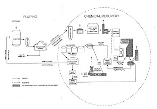
The relationship of the chemical recovery cycle to the pulping and product forming processes is
chemical reclaim pulp and paper process
Figure 2
shown in Figure 1. Process flow diagrams of the chemical recovery area at kraft and soda pulp mills are shown in Figures 1 and 2, respectively.

The purpose of the chemical recovery cycle is to recover cooking liquor chemicals from spent
cooking liquor. The process involves concentrating black liquor, combusting organic compounds, reducing inorganic compounds, and reconstituting cooking liquor.

Cooking liquor, which is referred to as "white liquor, is an aqueous solution of sodium hydroxide (Na01) and sodium sulfide (Na2S) that is used in the pulping area of the mill. In the pulping process, white liquor is introduced with wood chips into digesters, where the wood chips are "cooked" under pressure. The contents of the digester are then discharged to a blow tank, where the softened chips are disintegrated into fibers or "pulp. The pulp and spent cooking liquor are subsequently separated in a series of brown stock washers: Spent cooking liquor, referred to as "weak black liquor, from the brown stock washers is routed to the chemical recovery area. Weak black liquor is a dilute solution (approximately 12 to 15 percent solids) of wood lignins, organic materials, oxidized inorganic compounds (sodium sulfate (Na2SO4), sodium carbonate (Na2003)), and white liquor (Na2S and Na0H).

In the chemical recovery cycle, weak black liquor is first directed through a series of multiple-effect evaporators (MEE's) to increase the solids content to about 50 percent. The "strong. (or "heavy") black liquor from the MEE's is then either oxidized in the BLO system if it is further concentrated in a DCE or routed directly to a concentrator (NDCE). Oxidation of the black liquor prior to evaporation in a DCE reduces emissions of TRS compounds, which are stripped from the black liquor in the DCE when it contacts hot flue gases from the recovery furnace. The solids content of the black liquor following the final evaporator/concentrator typically averages 65 to 68 percent.

Concentrated black liquor is sprayed into the recovery furnace, where organic compounds are combusted, and the Na2SO4 is reduced to Na2S. The black liquor burned in the recovery furnace has a high energy content (13,500 to 15,400 kilojoules per kilogram (kJ/kg) of dry solids (5,800 to 6,600 British thermal units per pound {Btu/lb} of dry solids)), which is recovered as steam for process requirements, such as cooking wood chips, heating and evaporating black liquor, preheating combustion air, and drying the pulp or paper products. Particulate matter (PM) (primarily Na2SO4) exiting the furnace with the hot flue gases is collected in an electrostatic precipitator (ESP) and added to the black liquor to be fired in the recovery furnace. Additional makeup Na2SO4, or "saltcake," may also be added to the black liquor prior to firing.

Molten inorganic salts, referred to as "smelt," collect in a char bed at the bottom of the furnace. Smelt is drawn off and dissolved in weak wash water in the SDT to form a solution of carbonate salts called "green liquor," which is primarily Na2S and Na2CO3. Green liquor also contains insoluble unburned carbon and inorganic Impurities, called dregs, which are removed in a series of clarification tanks.

Decanted green liquor is transferred to the causticizing area, where the Na2CO3 is converted to NaOH by the addition of lime (calcium oxide [Ca0]). The green liquor is first transferred to a slaker tank, where Ca0 from the lime kiln reacts with water to form calcium hydroxide (Ca(OH)2). From the slake, liquor flows through a series of agitated tanks, referred to as causticizers, that allow the causticizing reaction to go to completion (i.e., Ca(OH)2 reacts with Na2CO3 to form NaOH and CaCO3).

The causticizing product is then routed to the white liquor clarifier, which removes CaCO3 precipitate, referred to as "lime mud." The lime mud, along with dregs from the green liquor clarifier, is washed in the mud washer to remove the last traces of sodium. The mud from the mud washer is then dried and calcined in a lime kiln to produce "reburned" lime, which is reintroduced to the slaker. The mud washer filtrate, known as weak wash, is used in the SDT to dissolve recovery furnace smelt. The white liquor (NaOH and Na2S) from the clarifier is recycled to the digesters in the pulping area of the mill.

At about 7 percent of kraft mills, neutral sulfite semi-chemical (NSSC) pulping is also practiced. The NSSC process involves pulping wood chips in a solution of sodium sulfite and sodium bicarbonate, followed by mechanical de-fibrating. The NSSC and kraft processes often overlap in the chemical recovery loop, when the spent NSSC liquor, referred to as "pink liquor," is mixed with kraft black liquor and burned in the recovery furnace. In such cases, the NSSC chemicals replace most or all of the makeup chemicals. For Federal regulatory purposes, if the weight percentage of pink liquor solids exceeds 7 percent of the total mixture of solids fired and the sulfidity of the resultant green liquor exceeds 28 percent, the recovery furnace is classified as a "cross-recovery furnace.'" Because the pink liquor adds additional sulfur to the black liquor, TRS emissions from cross recovery furnaces tend to be higher than from straight kraft black liquor recovery furnaces.

With over 70 years experience, Thompson Equipment Company, Inc. (TECO) provides specialized instrumentation, magnetic flow meters, and re-manufactured process instruments used in the pulp and paper industry. For information on process control instruments, valves, or service or calibration, visit http://www.teco-inc.com or call 800-528-8997.

Understanding Why Cavitation and Flashing are Bad for Control Valves and Pumps

cavitation
Cavitation is caused by bubbles collapsing asymmetrically
at very high speeds, producing extremely high
pressures in very small areas. 
Fluid passing through a control valve experiences changes in velocity as it enters the narrow constriction of the valve trim (increasing velocity) then enters the widening area of the valve body downstream of the trim (decreasing velocity). These changes in velocity result in the fluid molecules’ kinetic energies changing as well. In order that energy be conserved in a moving fluid stream, any increase in kinetic energy due to increased velocity must be accompanied by a complementary decrease in potential energy, usually in the form of fluid pressure. This means the fluid’s pressure will fall at the point of maximum constriction in the valve (the vena contracta, at the point where the trim throttles the flow) and rise again (or recover) downstream of the trim.

If fluid being throttled is a liquid, and the pressure at the vena contracta is less than the vapor pressure of that liquid at the flowing temperature, the liquid will spontaneously boil. This is the phenomenon of flashing. If, however, the pressure recovers to a point greater than the vapor pressure of the liquid, the vapor will re-condense back into liquid again. This is called cavitation.

As destructive as flashing is to a control valve, cavitation is worse. When vapor bubbles re-condense into liquid they often do so asymmetrically, one side of the bubble collapsing before the rest of the bubble. This has the effect of translating the kinetic energy of the bubble’s collapse into a high-speed “jet” of liquid in the direction of the asymmetrical collapse. These liquid “microjets” have been experimentally measured at speeds up to 100 meters per second (over 320 feet per second). What is more, the pressure applied to the surface of control valve components in the path of these microjets is intense. Each microjet strikes the valve component surface over a very small surface area, resulting in a very high pressure (P = F/A ) applied to that small area. Pressure estimates as high as 1500 newtons per square millimeter (1.5 giga-pascals, or about 220000 PSI!) have been calculated for cavitating control valve applications involving water.

Watch the video below to better understand the impact of cavitation on a process flow system.

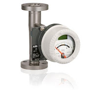
Basics of Variable Area Flowmeters

Variable Area Flowmeter (Rotameter)
Rotameter (ABB)
Flowmeters are a class of devices or instruments used to measure rate of fluid flow. Flow measurement stands as a vital input to many process operations across almost every industry. Applications can range from precise measurement of very small gas flows to oil or water flows through large diameter piping systems. There are a number of technologies employed for measuring fluid flow, each with attributes of design, performance, or cost that can make them an advantageous choice for a particular application.

Variable-area flowmeters are designed to measure flow using a precisely fabricated obstruction in the flow path that is repositioned in a tapered flow tube by changes in fluid flow.

Variable Area Flowmeter (Rotameter)
Rotameter (ABB
A rotameter is a flow indicator consisting of a tapered tube containing a plummet. The plummet is generally a solid object and sometimes referred to as a float. Rotameters rely on gravity as part of their operating principle, so the instrument must be installed such that the inlet is at the bottom and fluid flows directly upward through the tapered tube. As fluid flows through the tube, a pressure differential develops across the plummet. This creates an upward force on the plummet, moving the plummet in the direction of the flow. The flow area around the plummet increases as it moves from the narrow portion of the flow tube to a wider portion up the measurement scale. As the available flow space around the plummet increases, the upward force on it decreases. Eventually, the equalization between the pressure force and the weight of the plummet occurs and the float stops moving. The flow rate is indicated by the plummet's position relative to a pre-calibrated scale printed along the length of the tube. The same type of system can be used to measure liquid or gas flow, with the rotameter being specifically calibrated for the fluid to be measured. It is common to employ a rotameter with an integral needle valve as a metering device for delivering a precise fixed flow of a fluid into a process.

These devices are generally inexpensive and easy to apply. Key application considerations include a vertical installation orientation, matching the rotameter to the fluid, and providing physical access to read the indicated flow.

Industries use rotameters primarily as indicating devices. Rotameters enjoy a wide range of applications throughout research and manufacturing processes. Share your flow measurement challenges with instrumentation specialists, combining your own process knowledge and experience with their product application expertise to develop effective solutions.

Industrial Valve Basics: Rotary Ball Valves

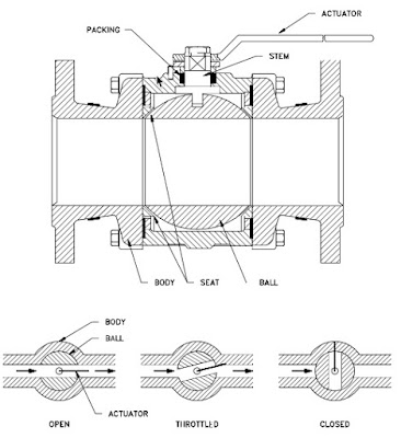
Ball valve
Cut-away view of ball
valve components:

1) Body
2) Seat
3) Foating ball 
4) Lever handle 
5) Stem

(Image courtesy of Wikipedia)
A ball valve is a rotational motion valve that uses a ball-shaped disk to stop or start fluid flow. The ball, performs the same function as the disk in the globe valve. When the valve handle is turned to open the valve, the ball rotates to a point where the hole through the ball is in line with the valve body inlet and outlet. When the valve is shut, the ball is rotated so that the hole is perpendicular to the flow openings of the valve body and the flow is stopped.

Most ball valve actuators are of the quick-acting type, which require a 90° turn of the valve handle to operate the valve. Other ball valve actuators are planetary gear-operated. This type of gearing allows the use of a relatively small handwheel and operating force to operate a fairly large valve.

Some ball valves have been developed with a spherical surface coated plug that is off to one side in the open position and rotates into the flow passage until it blocks the flowpath completely. Seating is accomplished by the eccentric movement of the plug. The valve requires no lubrication and can be used for throttling service.

Advantages

A ball valve is generally the least expensive of any valve configuration and has low maintenance costs. In addition to quick, quarter turn on-off operation, ball valves are compact, require no lubrication, and give tight sealing with low torque.

Disadvantages

Conventional ball valves have relatively poor throttling characteristics. In a throttling position, the partially exposed seat rapidly erodes because of the impingement of high velocity flow.

Typical Ball Valve
Typical Ball Valve (click for larger view).

Port Patterns

Ball valves are available in the venturi, reduced, and full port pattern. The full port pattern has a ball with a bore equal to the inside diameter of the pipe.

Valve Materials


Balls are usually metallic in metallic bodies with trim (seats) produced from elastomeric (elastic materials resembling rubber) materials. Plastic construction is also available.

The resilient seats for ball valves are made from various elastomeric material. The most common seat materials are teflon (TFE), filled TFE, Nylon, Buna-N, Neoprene, and combinations of these materials. Because of the elastomeric materials, these valves cannot be used at elevated temperatures. Care must be used in the selection of the seat material to ensure that it is compatible with the materials being handled by the valve.

Ball Valve Stem Design

The stem in a ball valve is not fastened to the ball. It normally has a rectangular portion at the ball end which fits into a slot cut into the ball. The enlargement permits rotation of the ball as the stem is turned.

Ball Valve Bonnet Design

A bonnet cap fastens to the body, which holds the stem assembly and ball in place. Adjustment of the bonnet cap permits compression of the packing, which supplies the stem seal. Packing for ball valve stems is usually in the configuration of die-formed packing rings normally of TFE, TFE-filled, or TFE-impregnated material. Some ball valve stems are sealed by means of O-rings rather than packing.

Ball Valve Position

Some ball valves are equipped with stops that permit only 90° rotation. Others do not have stops and may be rotated 360°. With or without stops, a 90° rotation is all that is required for closing or opening a ball valve.

The handle indicates valve ball position. When the handle lies along the axis of the valve, the valve is open. When the handle lies 90° across the axis of the valve, the valve is closed. Some ball valve stems have a groove cut in the top face of the stem that shows the flowpath through the ball. Observation of the groove position indicates the position of the port through the ball. This feature is particularly advantageous on multiport ball valves.


For more information about any style industrial valve, contact TECO at 800-528-8997 or visit http://www.teco-inc.com.