What Are Rotameters?

rotameter
Rotameter (ABB)
Rotameters are a type of variable area flow meter used for measuring the volumetric flow rate of a fluid. A tapered tube, usually glass, has a float that gets pushed by the drag force of the flow being measured and is pulled down by gravity. The simple operating principle and design makes rotameters a popular choice, and they are able to measure high flow rates as well as very low flow rates.

The rotameter has a number of advantages for use in a process. No external power or fuel is required, only the corresponding flow and gravity. They are simple devices that can be produced from low-cost materials, which is a main reason for the rotameter’s widespread use across many applications. Additionally, the area of the flow passage increases when the float moves, resulting in a linear relationship. The clear glass used also allows for a low risk of thermal shock and resulting issues from measuring chemicals. Rotameters also typically do not experience large drops in pressure, are simple to install, and are repeatable for long periods of time as long as they are operating under the same process conditions.

A few limitations exist in rotameters, the first of which relates to the fact the rotameter relies on displacement to function. A rotameter made to measure a certain substance at a particular temperature is only going to be accurate when measuring the substance and process qualities originally intended. While a rotameter can be scaled to measure different densities and viscosities, a limitation exists when the fluid characteristics being measured change in complexity. Secondly, while floats are often designed to function independent of viscosity, it can be difficult to ensure their effectiveness. Additionally, measurements being evaluated via rotameters can be uncertain when the float oscillates or near the bottom of the scale being used by the rotameter.

Certain fluids may also obscure the reading on the rotameter since the reading must be read through the flowing medium. This limitation can be countered by coupling he rotameter with a transducer in certain process applications. Another option for readability involves using a magnetic float that can be accompanied by a follower outside the tube, allowing the operator to easily read the measurement.

For more information about rotameters, visit https://teco-inc.com/ABB.

Positive Displacement Flowmeters

Positive displacement flowmeter.
(Badger Meter Blancett)
Positive displacement flowmeters use fluid to mechanically move internal components such as pistons, gears and discs to measure flow.  These devices are both precise and simple to operate.

The positive displacement flowmeter, in contrast with other types of flowmeters, directly measure the volume of fluid passing through the meter instead of employing inferential flow measurement. The rotational velocity of the rotor in the flow meter is directly proportional to the rate of flow. Electronic versions of positive displacement meters rely on magnets to activate sensors in their fluid chambers, whereas their non-electrical counterparts rely on the rotation being driven by the fluid flow.

The operating principle of the positive displacement meter may be simple, yet the flowmeter type offers a few specific advantages for industrial application. A main benefit of this flowmeter is a high level of accuracy due to its internal components. The accuracy of the flowmeter is directly related to the size of the clearances, or the space between the sealing faces.

These flowmeters are also particularly useful for handling a high range of viscosities. As the fluid viscosity increases with the positive displacement meter, less slippage or bypass will occur, meaning more total fluid will pass through the positive displacement meters. In addition to these design-based advantages, the positive displacement meter typically allows for excellent repeatability and linearity.

The longstanding use of positive displacement flowmeters across various industries has been a source of stability in terms of design, with the most recent advancements in positive displacement technology focusing on maintaining precision at lower costs.

There are a few known limitations for the use of positive displacement meters. The meters are not the optimal choice for measuring fluids with large particles, and are also non-ideal for measuring fluids with large air pockets. Additionally, systems using positive displacement meters need to account for slight pressure drops in the positive displacement meter. While the meters are able to accurately measure non-lubricating fluids, using positive displacement flowmeters to measure these types of liquids will not be as efficient as using the flowmeter for lubricating fluids. Overall, these types of flowmeters are a cost effective, accurate and volumetrically based flow measurement solution.

For more information on positive displacement flowmeters, call Thompson Equipment Company (TECO) at 800-528-8997 or visit https://teco-inc.com.


An Easy Way to Understand Laminar Flow vs. Turbulent Flow

Image courtesy of Wikimedia.org
Laminar flow occurs when a fluid flows in parallel "layers" with no interaction between the layers. When flowing at low velocities, fluids tend to flow without lateral (sideways) mixing, and adjacent layers glide past one another, analogous to playing cards sliding between others in a deck.

In contrast to laminar flow, turbulent flow, caused by excessive kinetic energy in parts of a fluid flow, undergoes mixing and lateral irregularities characterized by eddies, recirculation, and apparent randomness. Fluid speed magnitude and direction changes chaotically in turbulent flow.

The video below provides a very simple, but very effective, demonstration of laminar and turbulent flow.

https://teco-inc.com
800-528-8997

Get Your Process Flow Meters Remanufactured Instead of Buying New

Remanufactured Flow Meters
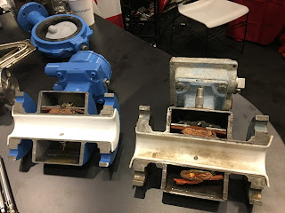
Cutaway before and after of remanufactured flow meter.
Head scratcher. Why buy brand new flow meters when there are companies in the USA that have the trained technicians and facilities ready to remanufacture your old flow meters to a condition better than new?

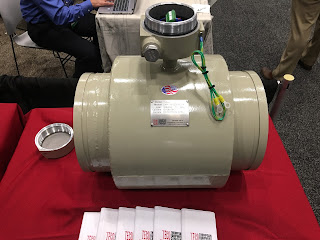
Remanufactured flow meters meet or exceed all OEM specifications and performance standards. Here's how it works. Experienced technicians break down your flow meter to it's core components - flowtube, electronics, enclosure, flanges, and electrical. All parts are evaluated for wear and tear. All components are cleaned, primed, and painted. New electronics, flow sensors, liners, and electrical connections are installed. Once assembly is complete, the "remanufactured" flow meter goes through an exhaustive quality control process and is calibrated to NIST traceable standards using an advanced, state-of-the-art calibration facility.

remanufactured flow meter
Remanufactured flow meter.
All this is done very efficiently, quickly and cost-effectively.  You just ship your old instrument in to the attention of the "Repair Department". No RMA is required. The company evaluates your old flow meter and then generates a quote with delivery time for the remanufactured meter (normally within 48 hours).

Here is a summary of the benefits for choosing remanufacturing:
  • All brands of flow meters are candidates.
  • NIST traceable certificate is provided.
  • Obsolete flow meters are no problem.
  • No evaluation fees charged.
  • Accessories are included.
  • New warranty is given.
  • Failure analysis is provided.
  • Flow meters can be repurposed for severe service (enhanced during remanufacturing).
  • Remanufacturing is GREEN and environmentally friendly.
For more information, visit this flow meter remanufacturing link or call 800-528-8997.

Industrial Plug Valves

plug valve
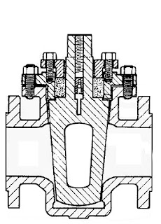
Plug valve diagram showing
plug shape and orifice.
There are common components to be found on almost every process system that involves fluid control. Regardless of the operation's scale, pumps, piping, tanks and valves are likely to be part of the system.

Valves, of which there are many types, provide control over the flow rate, direction and routing of fluids in a processing operation. Flow can be started, stopped or modulated between zero and full rate using a properly sized and configured valve. Some valves enable media flow to be diverted to a selection of outlets, in lieu of a single inlet and outlet pair. Specialized valves regulate inlet or outlet pressure, or prevent fluid flow from going in an undesirable direction. All of these capabilities are packaged into differing valve product offerings that present a very large selection array to a process designer or engineer.

Industrial flow control valve types are generally classified according to the structure or arrangement contained within the valve body that provides obstruction to fluid flow. Some of the common types are ball, butterfly, gate, globe, and plug. Surely, there are more valve types, and this article is not intended to list them all. Some of our previous blogs have discussed selection considerations for gate, ball and butterfly valves. This article will focus on one of the oldest valve types, the plug valve.

Plug valves, like ball and butterfly valves, span from fully open to fully closed positions with a shaft rotation of 90 degrees. The “plug” in a plug valve is installed in the flow path within the valve body and rotated by means of a stem or shaft extending to the exterior of the body. Plugs are often tapered toward the bottom and are fitted to a seating surface in the valve body cavity that prevents fluid from bypassing the plug. An opening through the plug, the port, can be shaped to provide particular flow characteristics. There are numerous variants of the basic plug valve which may make it suitable for particular applications. One common variant is the lined or sleeved plug valve, with an insert or interior lining of material that creates an isolating barrier between the valve body and the media. This allows use of less expensive materials for the body construction that may be otherwise subject to corrosion by exposure to aggressive media.

Plug valve advantages:
  • 90 degree rotation from open to closed provides fast operation.
  • With proper configuration, can be well suited for frequent operation.
  • Availability of corrosion resistant liner may provide comparative cost savings because valve body can be constructed of less expensive material.
  • Design is simple and employs a low parts count.
  • Valve can be serviced in place.
  • Generally, low resistance to flow when fully open.
  • Reliable leak-tight service due to tapered plug wedging action, replaceable sleeve, and injection of lubricant in some variants.
Plug valve disadvantages:
  • Higher friction in the plug closure mechanism may require comparatively higher operating torque than other valve types.
  • Without a specially designed plug, generally not well suited for throttling applications.
  • Rapid shutoff delivered by plug design may not be suitable for some applications where hammering may occur.
Share your fluid control application challenges with a valve and automation specialist. Leverage your own knowledge and experience with their product application expertise to develop an effective solution.

Contact Thompson Equipment (TECO) for all your valve automation and valve repair needs.

https://teco-inc.com
800-528-8997

What Are Orifice Plates?

Fig. 1 - Orifice Plates
The orifice plate is the simplest of the flowpath restrictions used in flow detection, as well as the most economical. Orifice plates are flat plates 1/16 to 1/4 inch thick. They are normally mounted between a pair of flanges and are installed in a straight run of smooth pipe to avoid disturbance of flow patterns from fittings and valves.

Three kinds of orifice plates are used: concentric, eccentric, and segmental (as shown in Figure 1).

The concentric orifice plate is the most common of the three types. As shown, the orifice is equidistant (concentric) to the inside diameter of the pipe. Flow through a sharp-edged orifice plate is characterized by a change in velocity. As the fluid passes through the orifice, the fluid converges, and the velocity of the fluid increases to a maximum value. At this point, the pressure is at a minimum value. As the fluid diverges to fill the entire pipe area, the velocity decreases back to the original value. The pressure increases to about 60% to 80% of the original input value. The pressure loss is irrecoverable; therefore, the output pressure will always be less than the input pressure. The pressures on both sides of the orifice are measured, resulting in a differential pressure which is proportional to the flow rate.

Segmental and eccentric orifice plates are functionally identical to the concentric orifice. The circular section of the segmental orifice is concentric with the pipe. The segmental portion of the orifice eliminates damming of foreign materials on the upstream side of the orifice when mounted in a horizontal pipe. Depending on the type of fluid, the segmental section is placed on either the top or bottom of the horizontal pipe to increase the accuracy of the measurement.

Eccentric orifice plates shift the edge of the orifice to the inside of the pipe wall. This design also prevents upstream damming and is used in the same way as the segmental orifice plate.
Orifice plates have two distinct disadvantages; they cause a high permanent pressure drop (outlet pressure will be 60% to 80% of inlet pressure), and they are subject to erosion, which will eventually cause inaccuracies in the measured differential pressure.

Contact TECO with any process flow question or requirement. You can find them by visiting https://teco-inc.com or by calling (504) 833-6381.

Industrial Control Valve Design and Operation

Control valves
The design and operation of industrial control valves  is very important to understand if you work as a process engineer, a plant maintenance person, or if you design process control loops.

Control valves are used extensively in power plants, pulp and paper mills, chemical manufacturing, petro-chemical processing, HVAC and steam distribution systems.

There are many types, manufacturers, body styles, and specialized features, but the they all share some basics operating principles. The video below explains components, operation, and fundamentals.

TECO designs automated control valve systems for all major industries including chemical, pulp and paper, petro-chemical, power generation, and water treatment.  TECO’s experience and engineering background make them a uniquely qualified partner for your next automated valve requirement.

https://www.teco-inc.com
800-528-8997