Introduction to Transmitters used in Process Control

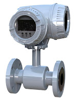
Flow transmitter
Flow transmitter (ModMag)
Transmitters are process control field devices. They receive input from a connected process sensor, then convert the sensor signal to an output signal using a transmission protocol. The output signal is passed to a monitoring, control, or decision device for use in documenting, regulating, or monitoring a process or operation.

In general, transmitters accomplish three steps, including converting the initial signal twice. The first step is the initial conversion which alters the input signal to make it linear. After an amplification of the converted signal, the second conversion changes the signal into either a standard electrical or pneumatic output signal that can be utilized by receiving instruments and devices. The third and final step is the actual output of the electrical or pneumatic signal to utilization equipment - controllers, PLC, recorder, etc.

Transmitters are available for almost every measured parameter in process control, and are often referred to according to the process condition which they measure. Some examples.

  • Pressure transmitters
  • Temperature transmitters
  • Flow transmitters
  • Level transmitters
  • Vibration transmitters
  • Current, voltage & power transmitters
  • PH, conductivity, dissolved gas transmitters, etc. 
  • Consistency

Consistency Transmitter
Consistency Transmitter(TECO)
Output signals from transmitters, when electrical, often are either voltage (1-5 or 2-10 volts DC) or current (4-20 mA). Power requirements can vary among products, but are often 110/220 VAC or 24 VDC.  Low power consumption by electrical transmitters can permit some units to be "loop powered", operating from the voltage applied to the output current loop. These devices are also called "two-wire transmitters" because only two conductors are connected to the unit. Unlike the two wire system which only needs two wires to power the transmitter and carry the analog signal output, the four-wire system requires four separate conductors, with one pair serving as the power supply to the unit and a separate pair providing the output signal path. Pneumatic transmitters, while still in use, are continuously being supplanted by electrical units that provide adequate levels of safety and functionality in environments previously only served by pneumatic units.

Pressure Transmitter
Pressure
Transmitter
(ifm)
Many transmitters are provided with higher order functions in addition to merely converting an input signal to an output signal. On board displays, keypads, Bluetooth connectivity, and a host of industry standard communication protocols can also be had as an integral part of many process transmitters. Other functions that provide alarm or safety action are more frequently part of the transmitter package, as well.

Wireless transmitters are also available, with some operating from battery power and negating the need for any wired connection at all. Process transmitters have evolved from simple signal conversion devices to higher functioning, efficient, easy to apply and maintain instruments utilized for providing input to process control systems.

To lean more about instrumentation and control, visit http://www.teco-inc.com or call Thompson Equipment at 800-528-8997.

ifm Industrial Sensors and Control Products

ifm Temperature sensor
ifm Temperature Sensor
ifm is one of the world’s largest manufacturers of industrial sensors and controls products, producing over 9 million sensors annually. Products include position sensors, sensors for motion control, vision sensors, safety technology, process sensors, and sensors for industrial networks.

Below is ifm's complete catalog to familiarize you with their products.

For assistance with ifm products, visit TECO's website, or call 800-528-8997 for immediate service.

Turbine Flowmeters

Turbine flowmeters use a free-spinning turbine wheel to measure fluid velocity, much like a miniature windmill installed in the flow stream. The fundamental design goal of a turbine flowmeter is to make the turbine element as free-spinning as possible, so no torque will be required to sustain the turbine’s rotation. If this goal is achieved, the turbine blades will achieve a rotating (tip) velocity directly proportional to the linear velocity of the fluid, whether that fluid is a gas or a liquid:
Diagram of turbine flowmeter

The mathematical relationship between fluid velocity and turbine tip velocity – assuming frictionless conditions – is a ratio defined by the tangent of the turbine blade angle:

For a 45o blade angle, the relationship is 1:1, with tip velocity equaling fluid velocity. Smaller blade angles (each blade closer to parallel with the fluid velocity vector) result in the tip velocity being a fractional proportion of fluid velocity.

Turbine tip velocity is quite easy to sense using a magnetic sensor, generating a voltage pulse each time one of the ferromagnetic turbine blades passes by. Traditionally, this sensor is nothing more than a coil of wire in proximity to a stationary magnet, called a pickup coil or pickoff coil because it “picks” (senses) the passing of the turbine blades. Magnetic flux through the coil’s center increases and decreases as the passing of the steel turbine blades presents a varying reluctance (“resistance” to magnetic flux), causing voltage pulses equal in frequency to the number of blades passing by each second. It is the frequency of this signal that represents fluid velocity, and therefore volumetric flow rate.

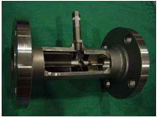
A cut-away demonstration model of a turbine flowmeter is shown in the following photograph. The blade sensor may be seen protruding from the top of the flowtube, just above the turbine wheel:

Turbine flowmeter
Turbine flowmeter cutaway
Note the sets of “flow conditioner” vanes immediately before and after the turbine wheel in the photograph. As one might expect, turbine flowmeters are very sensitive to swirl in the process fluid flowstream. In order to achieve high accuracy, the flow profile must not be swirling in the vicinity of the turbine, lest the turbine wheel spin faster or slower than it should to represent the velocity of a straight-flowing fluid. A minimum straight-pipe length of 20 pipe diameters upstream and 5 pipe diameters downstream is typical for turbine flowmeters in order to dissipate swirl from piping disturbances.

Mechanical gears and rotating cables have also been historically used to link a turbine flowmeter’s turbine wheel to indicators. These designs suffer from greater friction than electronic (“pickup coil”) designs, potentially resulting in more measurement error (less flow indicated than there actually is, because the turbine wheel is slowed by friction). One advantage of mechanical turbine flowmeters, though, is the ability to maintain a running total of gas usage by turning a simple odometer-style totalizer. This design is often used when the purpose of the flowmeter is to track total fuel gas consumption (e.g. natural gas used by a commercial or industrial facility) for billing.

For more information on turbine flowmeters, contact Thompson Equipment Company (TECO) by visiting their website at http://www.teco-inc.com or call 800-528-8997.

Reprinted from "Lessons In Industrial Instrumentation" by Tony R. Kuphaldt under the Creative Commons Attribution 4.0 International Public License.

Paper Production: Measuring Freeness Produces More Salable Product

Measuring Freeness improves quality
Measuring Freeness improves quality in paper production.
Better quality and more salable paper is the outcome of accurately measuring freeness at the beginning of the manufacturing process. Controlling freeness makes production lines more efficient and capable of producing better quality paper at a lower cost per ton.

According to the North Carolina State Mini-Encyclopedia of Papermaking Wet-End Chemistry, freeness is defined as “a measure of how quickly water is able to drain from a fiber furnish sample. In many cases there is a correlation between freeness values and either (a) a target level of refining of pulp, or (b) the ease of drainage of white water from the wet web, especially in the early sections of a Fourdrinier former. Standard tests of freeness are based on gravity dewatering through a screen. The devices are designed so that an operator can judge the speed of dewatering by observing the volume of liquid collected in a graduated cylinder. Freeness tends to be decreased by refining and by increases in the level of fines in the furnish. Freeness can be increased by use of drainage aids, removal of fines, or enzymatic treatments to convert mucilaginous materials into sugars."

TECO (Thompson Equipment Company) has been serving the pulp and paper industry for over 60 years, and has helped hundreds of clients with their unique Drainac® Drainage Rate Indication System. The Drainac® is an on-line instrument that continually measures the drainage rate of pulp and provides a proportional 4-20 mA DC signal. The unit consists of two major sub-assemblies; a detector and a detector control cabinet. It has earned a reputation as the fastest, lowest cost, and most pain-free device of its kind for measuring freeness.

Basic Applications

Closed Loop Refiner Controls – On-line freeness measurement is commonly used to control the final freeness target (setpoint) for the refiners by cascading the freeness measurement output directly to the horsepower tons / day controller.

Basic On-line Freeness Measurement – Basic on-line freeness measurement is used by production managers and paper machine operators as a “speedometer” of fiber quality enabling them to make real- time decisions that effect final production quality and paper machine run-ability.

Stock Blending – Used for monitoring the fiber characteristics of individual furnish streams so that optimal stock blending can be accomplished on a real-time basis. In this manner, the lower cost furnish stream can be maximized without sacrificing final product quality.

Please watch the video below for a better understanding of why its important to measure freeness for improved paper quality. For more information on freeness measurement, visit http://www.drainac.com or call TECO at 800-528-8997.


Introduction to Industrial Flowmeters

Magmeter
Magnetic flowmeter
(courtesy of Badger Meter)
Flowmeters measure the rate or quantity of moving fluids, in most cases liquid or gas, in an open channel or closed conduit. There are two basic flow measuring systems: those which produce volumetric flow measurements and those delivering a weight or mass based measurement. These two systems, required in many industries such as power, chemical, and water, can be integrated into existing or new installations. For successful integration, the flow measurement systems can be installed in one of several methods, depending upon the technology employed by the instrument. For inline installation, fittings that create upstream and downstream connections that allow for flowmeter installation as an integral part of the piping system. Another configuration, direct insertion, will have a probe or assembly that extends into the piping cross section. There are also non-contact instruments that clamp on the exterior surface of the piping add gather measurements through the pipe wall without any contact with the flowing media.
Turbine flowmeter
Turbine flowmeter
(courtesy of Badger Meter)

Because they are needed for a variety of uses and industries, there are multiple types of flowmeters classified generally into four main groups: mechanical, inferential, electrical, and other.

Quantity meters, more commonly known as positive displacement meters, mass flowmeters, and fixed restriction variable head type flowmeters all fall beneath the mechanical category. Fixed restriction variable head type flowmeters use different sensors and tubes, such as orifice plates, flow nozzles, and venturi and pitot tubes.
Rotameter
Variable area flowmeter
(courtesy of ABB)

Inferential flowmeters include turbine and target flowmeters, as well as variable area flowmeters also known as rotameters.

Laser doppler anemometers, ultrasonic flowmeters, and electromagnetic flowmeters are all electrical-type flowmeters.

TECO Flowmeter and Process Instrument Remanufacturing

As the world’s largest remanufacturer of flowmeters and process instruments, TECO has the experience, trained technicians, and facilities to remanufacture your equipment to meet or exceed all OEM specifications and performance standards.

TECO also has a "No Hassle Guarantee". Just send in your item, no form needed, no RMA required, and they'll respond in 48 hours.


http://www.teco-inc.com | 800-528-8997

An Introduction to Industrial Valve Actuators

Industrial Valve Actuators
Industrial Valves and Valve Actuators
Valves are essential to industries which constitute the backbone of the modern world. The prevalence of valves in engineering, mechanics, and science demands that each individual valve performs to a certain standard. Just as the valve itself is a key component of a larger system, the valve actuator is as important to the valve as the valve is to the industry in which it functions. Actuators are powered mechanisms that position valves between open and closed states; the actuators are controllable either by manual control or as part of an automated control loop, where the actuator responds to a remote control signal. Depending on the valve and actuator combination, valves of different types can be closed, fully open, or somewhere in-between. Current actuation technology allows for remote indication of valve position, as well as other diagnostic and operational information. Regardless of its source of power, be it electric, hydraulic, pneumatic, or another, all actuators produce either linear or rotary motion under the command of a control source.

Thanks to actuators, multiple valves can be controlled in a process system in a coordinated fashion; imagine if, in a large industrial environment, engineers had to physically adjust every valve via a hand wheel or lever! While that manual arrangement may create jobs, it is, unfortunately, completely impractical from a logistical and economic perspective. Actuators enable automation to be applied to valve operation.

Pneumatic actuators utilize air pressure as the motive force which changes the position of a valve. Pressurized-liquid reliant devices are known as hydraulic actuators. Electric actuators, either motor driven or solenoid operated, rely on electric power to drive the valve trim into position. With controllers constantly monitoring a process, evaluating inputs, changes in valve position can be remotely controlled to provide the needed response to maintain the desired process condition.

Manual operation and regulation of valves is becoming less prevalent as automation continues to gain traction throughout every industry. Valve actuators serve as the interface between the control intelligence and the physical movement of the valve. The timeliness and automation advantages of the valve actuators also serve as an immense help in risk mitigation, where, as long as the system is functioning correctly, critical calamities in either environmental conditions or to a facility can be pre-empted and quickly prevented. Generally speaking, manual actuators rely on hand operation of levers, gears, or wheels, but valves which are frequently changed (or which exist in remote areas) benefit from an automatic actuator with an external power source for a myriad of practical reasons, most pressingly being located in an area mostly impractical for manual operation or complicated by hazardous conditions.

Thanks to their versatility and stratified uses, actuators serve as industrial keystones to, arguably, one of the most important control elements of industries around the world. Just as industries are the backbones of societies, valves are key building blocks to industrial processes, with actuators as an invaluable device ensuring both safe and precise operation.

Thompson Equipment (TECO) specifies, designs, and fabricates complete valve automation solutions for a wide variety of industries. Contact TECO for your next valve automation requirement.