Valve Automation Professionals Will Save You Time and Money on Your Next Industrial Valve Project

Teco Valve Automation Expert
Local Distributors and Reps provide great value when
working on automated valve projects.
Local distributors and representatives who sell industrial valves, actuators and controls also provide services and equipment that will save you time, money, and help you achieve a better outcome for the entire project.

Projects requiring engineered valve systems are best completed and accomplished through the proper selection and application of the valves, actuators, positioners, limit switches and other associated components. A great resource exists, ready to provide a high level of technical knowledge and assistance, that can be easily tapped to help you with your project - the valve automation sales professional.

Consider a few of the things the valve automation professional brings to your project:

Product Knowledge: Valve automation professionals are current on product offerings, proper application technique, and product capabilities. They also posses  information on future product obsolescence and upcoming new designs. This type of information is not generally accessible to the public via the Internet.

Experience: As a project engineer, you may be treading on new ground regarding some aspects of your current valve system design assignment. There can be real benefit in connecting to an experienced and highly knowledgable source, with past exposure to your current challenges.

Access: Through a valve automation professional, you may be able to establish a connection to “behind the scenes” manufacturer contacts with essential information not publicly available. The rep knows people at the factories, a well as at other valve related companies, who can provide quick and accurate answers to your valve automation related questions.

Of course, any valve actuation or automation solution proposed are likely to be based upon the products sold by the representative. That is where considering and evaluating the benefits of any solution becomes part of achieving the best project outcome.

Develop a professional, mutually beneficial relationship with a local valve automation professional to make your design job go after, more efficiently, and more cost effective. Their success is tied to your success, and they are eager to help you.

Basics of Process Piping: Piping & Instrument Diagrams

P&ID's (piping & instrumentation diagrams), or Process and Control Flow Diagrams, are schematic representations of a process control system and used to illustrate the piping system, process flow, installed equipment, and process instrumentation and functional relationships therein.

P&ID’s can be very detailed and are generally the primary source from where instrument and equipment lists are generated and are very handy reference for maintenance and upgrades. P&ID’s also play an important early role in safety planning through a better understanding of the operability and relationships of all components in the system.

Intended to provide a “picture” of all of piping including the physical branches, valves, equipment, instrumentation and interlocks. The P&ID uses a set of standard symbols representing each component of the system such as instruments, piping, motors, pumps, etc.

For more information on any process instrument question or requirement, feel free to contact the application engineers at Thompson Equipment. For immediate service call 800-528-8997

Custom Magmeters for the Most Abrasive and Erosive Slurry Application

custom magmeter
Custom magnetic flowmeter with
engineered ceramic
brick liner.
When you have suspended solids, such as cement, coal, or fly ash, mixed with a liquid (such as water), a mud-like substance referred to as a “slurry” is formed. Measuring flow of slurries is often times challenging because of their abrasive nature and the wear and tear flowmeters experience. Add to the challenge a carrier fluid that is highly caustic or acidic, and the flow measurement task becomes geometrically more difficult.

In certain industries this situation is very common. Slurry processing applications in mining, dredging, pulp & paper, fracking, oil and gas exploration (drilling slurries - not the old or gas), and wastewater treatment all have areas that present a variety of highly erosive and corrosive slurries. In these situations off-the-shelf magnetic flowmeters won’t last, so consideration must be given to custom flowmeters built specifically to withstand the application’s unique requirements. A complete understanding of the composition of the chemical and particulate nature of the slurry and the flow conditions is critical.
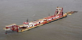
dredging
Dredging is an example of challenging slurry flow measurement. 

Customized magnetic flowmeters with very high erosion and abrasion resistance incorporate specialized materials and unique features that increase the performance and service life for that application. These flowmeters are highly engineered and the selection of a manufacturer with the experience, production capability, and quality control is imperative.

Here is a partial list of specialized features available from custom flowmeter manufacturers:

Specialty liners:

  • Magnesia stabilized Zirconia ceramic
  • Aluminum Oxide ceramic
  • Polyurethane rubber
  • Neoprene rubber
  • Linatex
  • Teflon (PTFE)
  • Rotationally molded Tefzel (ETFE)
  • PFA

Specialty electrodes: 

  • Stainless Steel
  • Hastalloy B/C
  • Titanium
  • Platinum/Iridium
  • Tungston Carbide

Exotic Tube Construction:

  • 100% Titanium
  • Marine Epoxy paints
  • Powder coating

In summary, when faced with measuring the flow of a highly erosive and abrasive slurry, it’s best to call upon a company with the expertise and production capabilities to match the flowmeter design exactly with the application requirements. Take the time to do this up front, and resist the temptation to “wing-it” with and install a generically designed flowmeter. Doing so will pay off in service life and overall cost in the long run.

The Operating Principles of a Magnetic Flowmeter

Below is a video, courtesy of Badger Meter, illustrating the operating principles of magnetic flowmeters (also known as magmeters).

A magnetic field is applied to the flow tube, resulting in an EMF proportional to the flow velocity passing perpendicular to the magnetic flux lines. The physical principle at work is Faraday's law of electromagnetic induction.

Magnetic flow meter requires a conductive fluid, and electrically insulated internal pipe surfaces to operate.

Advantages:
  • Low maintenance cost
  • No moving parts
  • Good for slurry
  • Good for corrosive fluids
  • Very linear
  • Minimal flow restriction

Disadvantages:
  • Requires electrically conductive fluids
For more information on magmeters, visit TECO at http://www.teco-inc.com of call 800-528-8997.

Variable Area Flowmeters (Rotameters)

Rotameter
ABB Rotameter
Variable area flowmeters (rotameters) are the most cost effective solution for almost all applications involving the measurement of industrial process liquids, gases or steam.

They meet the application requirements by featuring a wide range of design varieties and sizes. Technology proven, they offer a long life and high reproducibility. Variable area flowmeters are excellent mechanical back-up meters because no external power supply is needed.

TECO was the first firm to represent and sell the Fischer & Porter Rotameter Line, dating back to March, 1947.  With over 70 years of ABB Rotameter history, TECO is your best source to help with your rotameter applications.   http://www.teco-inc.com | 800-528-8997.

Understanding Coriolis Flow Measurement

Thompson Equipment
Coriolis flowmeters directly measure the mass flow of a subject fluid, which is inclusive of regular and supercritical liquids and liquefied gases. Operating on the Coriolis effect principle, Coriolis flowmeters create a controlled condition in which the mass flow of the fluid can be directly measured. They rely on motion mechanics: one or two tubes are aligned inside a Coriolis flowmeter, then made to oscillate with an exciter. Fluid flows through the oscillating tubes, twisting them slightly in proportion to the mass flow of the fluid and its inertia. There are highly reactive sensors attached to the tubes; when the measured substance flows through the vibrating tubes, the numeric difference between sensor readings provide the basis of the resulting fluid is mass flow measurement. This process also delivers a second measurement: the density of the substance. The sensors measure the frequency of oscillations. Coriolis flowmeters rely on direct computation instead of an algorithm, and therefore are regarded as highly accurate instruments in industry, coming in at 0.1 percent accuracy in some cases.
Coriolis principles
Rotation without mass flow
(image courtesy of Wikipedia).
Coriolis principles
Rotation with mass flow
(image courtesy of Wikipedia).
Coriolis flowmeters are advantageous choices for many industrial applications. They are used to measure drinking water, oils and gases, chemicals, etc. However, these mass flow measurement products particularly stand out in the chemical industry. As a prerequisite for most fluid processing operations, measurements and quantities often rely upon mass instead of upon volume. Coriolis flowmeters, with their direct measurement of mass flow, can be the optimal choice for applications requiring mass flow measurement.

As beneficial as Coriolis flowmeters are, they are not immune to some engineering and practical limitations. The most recognized limitation is the size of the pipes the meters are able to accommodate. A Coriolis meter is comparatively large, when other measurement instrument technologies are considered, making it difficult to place in some installations. In addition to being recognized as one of the most accurate flow measuring technologies, the Coriolis flowmeter requires little maintenance.
Coriolis principles
The vibration pattern with mass flow
(image courtesy of Wikipedia).
The vibration pattern during no-flow
(image courtesy of Wikipedia).

Selecting and configuring the instrument properly and assuring that installation is performed in accordance with manufacturer instructions are necessary tasks to achieving best instrument performance. Reach out to an instrumentation specialist with your flow measurement challenges, combining your process knowledge with their product application expertise to develop effective solutions.

For additional information on any industrial flow measuring technologies visit Thompson Equipment (TECO) at  http://www.teco-inc.com or call 800-528-8997.


An Introduction to Ultrasonic Flow Technology

How Ultrasonic energy is used to measure flow
How Ultrasonic energy
is used to measure flow.
Ultrasonic energy flow meters measure, via sound waves, the velocity of liquid flowing through a pipe––however, this pipe includes not just the traditional “pipe” but also mass flow chutes or something with open channels, free surfaces.

There are three different types of ultrasonic energy measuring tools, called flow meters: the first is the Open Channel flow meter which receives its calculations by computing geometrical distance; the second is the Doppler shift flow meter which reflects ultrasonic beams off sonically reflective materials, e.g. air bubbles; the third is the contrapropogating transit-time flow meter or, more recognizably, the transmission flow meter. The transmission flow meter has two versions: the in-line and the clamp-on. The former is “intrusive” whereas the latter is not, an outward device. These 72+ inch tools, using ultrasound technology, have the ability to measure fluids in bulk, all with distinct properties and principles., The use of this technology is most used in the respective oil and nuclear industries, wastewater technologies, pharmaceutical applications, and the food and beverage industry.

For intrusive flow meters, sensors are fitted opposite one another and alternate bouncing ultrasonic signals back and forth in the pipe, in an almost tennis-like format. In an elementary explanation, by increasing the number of sensors, engineers are able to decipher flow proportions through calculations of velocity between sensory transmissions; thereby, the flow volume can be computed.

For unintrusive flow meters, a literal clamp-on flow meter is placed atop the pipe so as not to interrupt flow. One of the most special properties uninstrusive flow meters offer is the ability to bounce ultrasonic sensors through piping up to four meters in diameter; this makes seemingly impossible feats possible, especially in otherwise difficult fields, e.g. hydroelectric.

Although the technology is pervasive, there are disadvantages still as there are advantages. However, the majority of the equipment’s disadvantages are unavoidable, such as costs and apparatus sensitivities. Nonetheless, there is also the threat of low ultrasonic accuracy, or attenuation, dependent on what systems are used and under what circumstances and command. Alternatively, one of the most publicized advantages is that ultrasonic energy flow technology is used for custody transfer of natural gases and petroleum liquids. Custody transfer usually entails following industry, national, and government standards and regulations. Ultrasonic energy flowmeters and analyzers are also relatively low maintenance, e.g. self-diagnosing. The technology has the capability to control and manage high pressures as well as high temperatures, and, being a popular application among engineers, manufacturers and the like, is reliable in its performance and consistency.

For more information on any industrial flow application, contact TECO at 800-528-8997 or visit www.teco-inc.com.