Clamp-on, Ultrasonic Flow Meters


Ultrasonic meters measure flow rate by propagating ultrasound waves into liquid filled pipes and measuring the reflections. There are two technologies to choose from based on the fluid properties; Transit Time and Doppler

Transit Time - Clean fluids with small amounts of suspended solids or aeration.

For clean fluids with small amounts of suspended solids or aeration, transit time ultrasonic meters provide the best performance and can be used in a wide range of applications for pipes 1/2 inch and larger.


Transit time flow meters have two transducers, which function as both ultrasonic transmitters and receivers. The flow meters operate by alternately transmitting and receiving a frequency modulated burst of ultrasound energy between the two transducers. The burst is first transmitted in the direction of fluid flow and then against fluid flow. Since ultrasound energy in a moving liquid is carried faster when it travels in the direction of fluid flow (downstream) than it does when traveling against fluid flow (upstream), a differential in the times of flight will occur. The ultrasound's time of flight is accurately measured in both directions, and the difference in time of flight is used to determine the velocity of the fluid.

Doppler Flow Meters - Fluids with suspended solids.

For fluids with significant amount of particles or air bubbles, such as slurries, sewage and plastics, Doppler ultrasonic meters provide the best performance.


Each Doppler flow meter utilizes two separate transducer heads. Ultrasonic waves are transmitted from one transducer and reflected by reflectors suspended within the liquid and then recorded by a receiving transducer.  If the reflectors are moving within the ultrasound transmission path, ultrasound waves will be reflected at a frequency shifted (Doppler shift) from the transmitted frequency.  The difference between the transmitted frequencies and reflected frequencies is directly proportional to the speed of the ultrasonic reflectors.

For more information about clamp-on ultrasonic flow meters, contact Thompson Equipment Company. Call them at 800-528-8997 or visit their web site at https://teco-inc.com.

Honoring the People Who Protect Our Freedom

Veterans Day

Through the observance of Veterans Day we celebrate and honor America's veterans for their patriotism, love of country, willingness to serve, and sacrifice for the common good. We recognize and celebrate those who have chosen to serve in the United States military and take an oath to defend the United States and our Constitution, from all enemies, foreign and domestic.

Veterans Day was originally called Armistice Day because of the November 11 Armistice that ended World War I. In 1954 it was officially changed to Veterans Day to include Veterans of all wars. Thompson Equipment Company thanks our Veterans, past and present, for serving our country and protecting our freedom.

What Are Valve Actuators?

Valve actuators are categorized based upon a number of factors including power source available,  torque necessary to operate the valve, installation location,  and the need for automatic actuation.  Actuators are devices which supply the force and motion to open and close valves. They can be manually, pneumatically, hydraulically, or electrically operated. In common industrial usage, the term actuator generally refers to a device which employs a non-human power source and can respond to a controlling signal.

Types of actuators include:


  • Manual handwheel or lever
  • Electrical motor
  • Pneumatic
  • Hydraulic

Gear Operator
Gear Operator

Manual Actuators

Manual actuators are capable of placing the valve in any position but do not permit automatic operation. The most common type mechanical actuator is the handwheel. This type includes handwheels fixed to the stem, hammer handwheels, and handwheels connected to the stem through gears.

Gear Operators

If additional mechanical advantage is necessary for a manually-operated valve, the valve bonnet is fitted with manually-operated gear heads as illustrated in Figure 32. A special wrench or handwheel attached to the pinion shaft permits one individual to operate the valve when two individuals might be needed without the gear advantage. Because several turns of the pinion are necessary to produce one turn of the valve stem, the operating time of large valves is exceptionally long. The use of portable air motors connected to the pinion shaft decreases the valve operating time.

Electric Actuators

Electric Actuator
Electric Actuator
Electric motors permit manual, semi-automatic, and automatic operation of the valve. Motors are used mostly for open-close functions, although they are adaptable to positioning the valve to any point opening as illustrated in Figure 33. The motor is usually a, reversible, high speed type connected through a gear train to reduce the motor speed and thereby increase the torque at the stem. Direction of motor rotation determines direction of disk motion. The electrical actuation can be semi-automatic, as when the motor is started by a control system. A handwheel, which can be engaged to the gear train, provides for manual operating of the valve. Limit switches are normally provided to stop the motor automatically at full open and full closed valve positions. Limit switches are operated either physically by position of the valve or torsionally by torque of the motor.


Pneumatic Actuators

Pneumatic Actuator
Pneumatic Actuator
Pneumatic actuators as illustrated in Figure 34 provide for automatic or semi- automatic valve operation. These actuators translate an air signal into valve stem motion by air pressure acting on a diaphragm or piston connected to the stem. Pneumatic actuators are used in throttle valves for open-close positioning where fast action is required. When air pressure closes the valve and spring action opens the valve, the actuator is termed direct- acting. When air pressure opens the valve and spring action closes the valve, the actuator is termed reverse- acting. Duplex actuators have air supplied to both sides of the diaphragm. The differential pressure across the diaphragm positions the valve stem. Automatic operation is provided when the air signals are automatically controlled by circuitry. Semi-automatic operation is provided by manual switches in the circuitry to the air control valves.

Hydraulic Actuators


Hydraulic Actuator
Hydraulic Actuator
Hydraulic actuators provide for semi-automatic or automatic positioning of the valve, similar to the pneumatic actuators. These actuators use a piston to convert a signal pressure into valve stem motion. Hydraulic fluid is fed to either side of the piston while the other side is drained or bled. Water or oil is used as the hydraulic fluid. Solenoid valves are typically used for automatic control of the hydraulic fluid to direct either opening or closing of the valve. Manual valves can also be used for controlling the hydraulic fluid; thus providing semi-automatic operation.

For more information on valve actuators and valve automation, contact Thompson Equipment Company (TECO) by calling 800-528-8997  of visit the valve automation area of their web site here.

The Top 10 Fluid Flow Measurement Application Questions

Fluid Flow Measurement
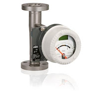
Variable area flowmeter
Variable area flow meter (ABB)
Measurement of flow is essential for operation, control, and record keeping for chemical manufacturing, water treatment, oil and gas production, refining, and many other processes. The accurate and reliable measurement of flow is essential to ensuring the proper and efficient operation of any flow control loop. Various technologies such as Coriolis, differential pressure, vortex, magnetic, ultrasonic, turbine and positive displacement meters can be used to measure flow. All of these technologies have advantages and disadvantages. Understanding the differences can be the difference in a successful flow meter implementation or a failure.  Before the proper technology can be selected, there are 10 basic application question that must be answered. They are:
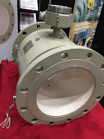
Severe service flow meter
(TECO)
  1. Is the measured process media a liquid or a gas?
  2. Is the flow measurement occurring in a pipe or in an open channel?
  3. What is the the flow rate?
  4. How much does the flow vary?
  5. If liquid,  is it clean or does it contain suspended solids or air bubbles?
  6. What accuracy is required?
  7. How much head loss by the flowmeter is permissible? 
  8. Is the flow corrosive or erosive?
  9. What types of flowmeter technologies can be accommodated in the location?
  10. What types of post installation service is available in area?
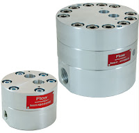
Positive Displacement Meter
Positive Displacement Meter (Blancett)
Selecting and configuring a flow measurement device properly, and assuring that installation is done correctly, are necessary tasks to achieving optimal flow meter performance. Reach out to a flow meter specialist with your flow application. By combining your process knowledge with their product application expertise, an effective and long lasting solution will result.

For more information about any flow measurement application, contact Thompson Equipment. The can be reached by calling 800-528-8997 or by visiting https://teco-inc.com.

Flow Measurement for Hydraulic Fracturing and the Production of Shale Gas

Figure 1. Illustration of the fracing (fracking) process.
(Image courtesy of EPA.gov)
A “conventional” gas reservoir is produced from sands and carbonates (such as limestone). In the conventional reservoir, the gas is in interconnected pore spaces, much like a kitchen sponge, that allow easier flow to a well.  In an "unconventional" gas reservoir, such as shale, the reservoir must be mechanically “stimulated” to create additional permeability and free the gas for collection.  Permeability refers to the capacity of a porous, sediment, soil – or rock in this case – to transmit a fluid. Unconventional reservoirs include tight gas (low-porosity sandstones and carbonate reservoirs) and coal bed methane (CBM – gas produced from coal seams).

For shale gas, hydraulic fracturing (known as "fracing" or "fracking") of a reservoir is the preferred stimulation method (figure 1). This typically involves injecting pressurized fluids to stimulate or fracture shale formations and release the natural gas. Sand pumped in with the fluids (often water) helps to keep the fractures open. The type, composition and volume of fluids used depend largely on the geologic structure, formation pressure and the specific geologic formation and target for a well. If water is used as the pressurized fluid, as much as 20 percent can return to the surface via the well (known as flow back). This water can be treated and reused – in fact, reuse of flow back fluids for subsequent hydraulic fracture treatments can significantly reduce the volume of wastewater generated by hydraulic fracturing. 

The hydraulic fracturing process was used in conventional limestone and sandstone reservoirs for decades before the onset of the shale revolution. But it was not until the 1970s that significant attempts to apply the technology to gas shale were made, pioneered by DOE research and demonstration project cost-sharing with industry in such ventures as the Eastern Gas Shales Project (1976-92).

Another major technology often employed in producing natural gas from shale is horizontal drilling. The shallow section of shale wells are drilled vertically (much like a traditional conventional gas well). Just above the target depth – the place where the shale gas formation exists – the well deviates and becomes horizontal. At this location, horizontal wells can be oriented in a direction that maximizes the number of natural fractures intersected in the shale. These fractures can provide additional pathways for the gas that is locked away in the shale, once the hydraulic fracturing operation takes place.

Accurate flow measurement is important in fracking applications and required for reliable data reporting to supervisory agencies. The preferred technology for measuring flow in fracking applications are magnetic flowmeters (magmeters), primarily for their non-obstructive flow path, accuracy and reasonable cost. There are caveats associated with applying magmeters in fracking applications and selection of specialized flow meter components is required. Fracking sand is very erosive and chemicals mixed with the fracking water can be erosive. Any flow meter used in fracking applications must be rugged enough to withstand these harsh conditions. 

Flow meter designed for fracking
applications (as well as for other
abrasive slurries) by TECO.
An excellent solution that provides all the the virtues of magnetic flowmeters and overcomes performance and longevity issues referred to as "severe service flowmeters" or "slurry flow meters" designed with components matched specifically to withstand the mechanical and chemical abuse they will see. Their modifications include: 
  • A ceramic sleeved liner made of magnesia partially stabilized zirconia. This ceramic can handle the abrasion and chemical attack with very little degradation.
  • Highly polished, ultra-smooth Tungsten electrodes. The Tungsten provides outstanding wear resistance while the high-polish reduces electrical noise introduced in the electrode circuitry.
  • Special coatings, or paints, to provide exterior protection.
For more information on fracking (or fracing) magnetic flow meters, contact Thompson Equipment Company (TECO) by calling 800-528-8997 or visit https://teco-inc.com.


Source: How is Shale Gas Produced? https://www.energy.gov/fe/shale-gas-101

Handbook for Variable Area Flowmeters

This  “Handbook for Variable Area Flowmeters“, courtesy of ABB and Thompson Equipment, is a practical guide for the user with selection criteria for real applications (see Check List/Parameter Questionnaire), correction factors, Accuracy Classes, corrosion resistance tables and much more. A separate flyer with actual pictures demonstrate the application versatility.

Answers are provided to frequently asked questions about this measurement principle (see Page 20) and we have incorporated a preferential quick ship program for the most popular instrument versions.

We hope that this Handbook provides you with a practical selection guide; naturally our sales team is always ready to provide you with any personal assistance you may require.


Thompson Equipment (TECO)
800-528-8997
https://teco-inc.com